Pilz PSEN op4F-A-14-030/1 Скачать руководство пользователя страница 27

OPERATING MANUAL 

PSEN op4F/H-A series 


PSENopt Advanced RX Muting
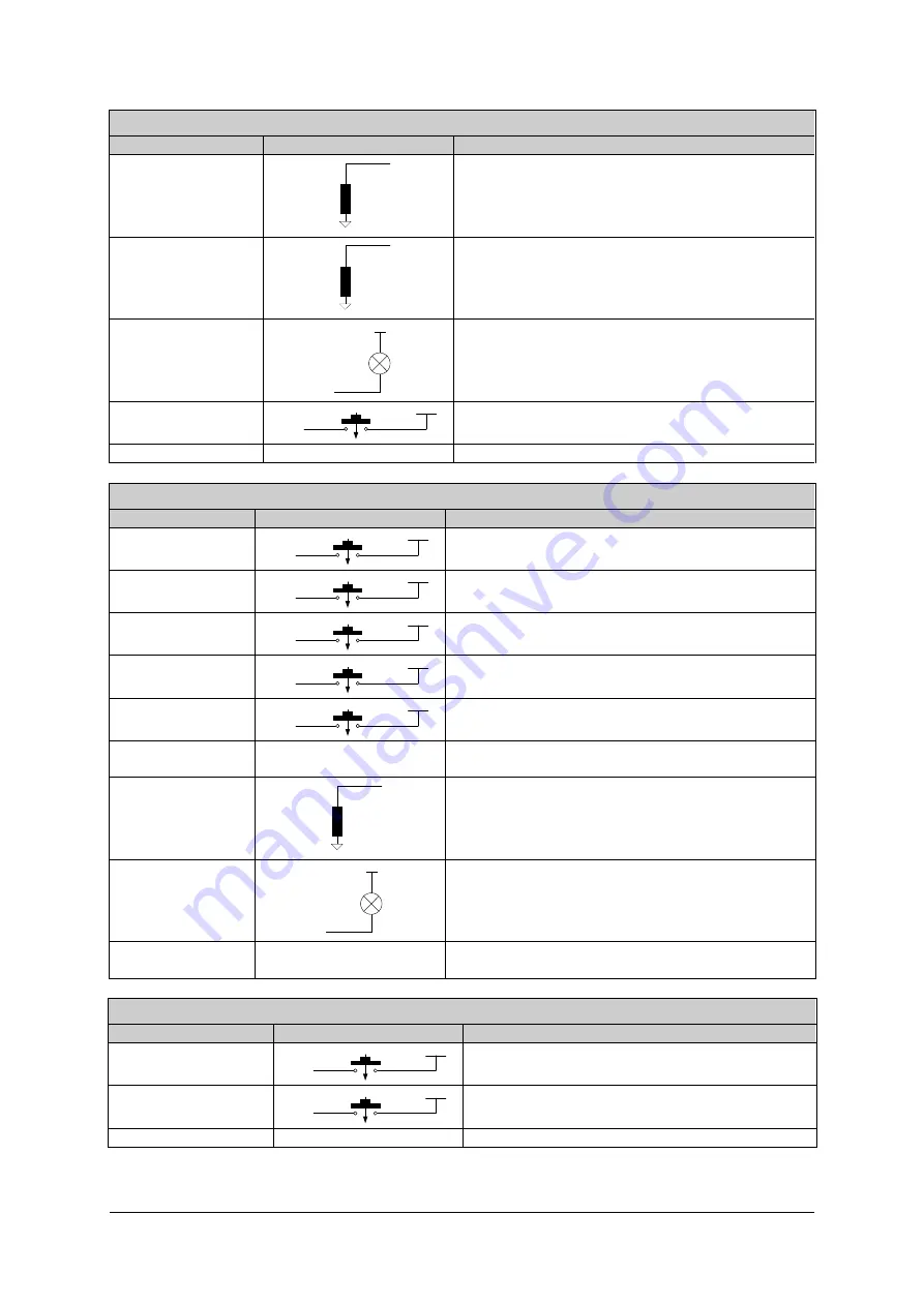
CONNECTION


LINE


BEHAVIOUR


OSSD1 / OSSD 2 

0V

OSSDs

Protected field clear 
No voltage = Protected field not clear 

OVERRIDE 
STATUS 

0V

OSSDs

High level = Override function active 
Low level = Override function inactive 

NOTE:  This line signals the state of the override 
signal inputs


MUTING LAMP 

24Vdc

LAMP

The open collector connection is activated when 
muting is activated. 

MUTING1/MUTING2 

24Vdc

IN line

N.O.

Is connected – when muting is active during 
operation 

FUNCTION EARTH 

Connect to earth 

PSENopt Advanced RX Blanking 

CONNECTION


LINE


BEHAVIOUR


RESET 

24Vdc

IN line

N.O.

Is connected – when in disabled state the 
RESET/RESTART/ALIGN button is operated 

RESTART 

24Vdc

IN line

N.O.

Is connected – when during operation the 
RESET/RESTART/ALIGN button is operated 

ALIGNMENT 

24Vdc

IN line

N.O.

Has to be set to 24 V DC at startup 

TEACH-IN 

24Vdc

IN line

N.O.

Is connected – when TEACH-IN button is operated 
during operation 

TOLERANCE 

24Vdc

IN line

N.O.

Has to be set to 24 V DC at startup 

EDM 

See Chapter 7.4 for 
connections 

Must be non-equivalent to OSSD during operation 
with EDM enabled 

OSSD1 / OSSD 2 

0V

OSSDs

Protected field clear 
No voltage = Protected field not clear 

BLANKING LAMP 

24Vdc

LAMP

The open collector connection is switched when 
blanking is activated. 

FUNCTION 
EARTH 

Connect to earth 

PSENopt Advanced TX 

CONNECTION


LINE


BEHAVIOUR


TEST 

24Vdc

IN line

N.O.

is connected, when the RESET button is 
operated during operation 

REDUCED RANGE 

24Vdc

IN line

N.O.

Has to be set to 24 V DC at startup 

FUNCTION EARTH 

Connect to earth 

1003067-EN-0

4

27

Содержание PSEN op4F-A-14-030/1

Страница 1: ...PSEN op4F H A series Operating Manual 1003067 EN 04 Safety light curtain...

Страница 2: ...KG Copies may be made for internal purposes Suggestions and comments for improving this documentation will be gratefully received Pilz PIT PMI PNOZ Primo PSEN PSS PVIS SafetyBUS p SafetyEYE SafetyNET...

Страница 3: ...ections following a first time installation 21 3 MECHANICAL ASSEMBLY 23 4 ELECTRICAL CONNECTIONS 25 4 1 Connection guidelines 28 5 ALIGNMENT 31 6 SETTING THE FUNCTIONS 33 6 1 Reset to factory configur...

Страница 4: ...LEDs 73 9 REGULAR CHECKS AND MAINTENANCE 76 9 1 Regular checks 76 9 2 Maintenance 76 10 TECHNICAL DETAILS 77 11 LIST OF AVAILABLE MODELS 78 12 DIMENSIONS 80 13 FITTINGS 81 14 ACCESSORIES 83 14 1 Rota...

Страница 5: ...transmitter and receiver are synchronised optically so the two units do not have to be connected directly to each other The infrared beams that are transmitted and received are controlled and monitor...

Страница 6: ...information you need regarding the functionality of the PSEN op4F H A safety light curtains and the safety regulations concerning correct installation 1 1 2 Package content The following components ar...

Страница 7: ...area of the protected field The resolution is closely linked to the part of the body that requires protection R 14 mm Finger protection Type 4 R 30 mm Hand protection Type 4 As shown in Fig 1 the res...

Страница 8: ...ht monitored by the PSEN op4F H A corresponds to the overall height of the light curtain With reference to the previous diagram the height of the protected field can be taken from the table below Mode...

Страница 9: ...danger zone until the hazardous machine movement has come to a standstill by triggering the light curtain In accordance with the standard ISO 13855 this distance depends on 4 factors Response time of...

Страница 10: ...to 2000 mm s if the calculated value S is 500 mm 1600 mm s if the calculated value S is 500 mm When using light curtains with a resolution of 40 mm the upper beam must be positioned at a height of 900...

Страница 11: ...of 35 ms for t1 t2 Machine s overall stopping performance in seconds C 8 d 14 for devices with resolution 40 mm D Resolution In each case if K 2000 mm sec then S 500 mm The safety distance will then n...

Страница 12: ...just one light axis on the safety light curtain PSEN op4F H A is interrupted during the downward phase the movable workpiece carrier is stopped immediately Benefits The simple installation options an...

Страница 13: ...imum safety distance S or that corresponds to it so that the operator cannot reach the danger zone until the movement of the hazardous object has come to a standstill by triggering the light curtain T...

Страница 14: ...ct to be detected must be greater than the device s resolution The light curtain must be installed in an environment that complies with the technical properties stated in Chapter 11 Smoke mist or dust...

Страница 15: ...son the safety light curtain must be installed at a height from which access to the danger zone can be covered in full Fig 6 Fig 5 Device positioned incorrectly Fig 6 Device positioned correctly Under...

Страница 16: ...ions can adversely affect how the object is detected within the protected area If the receiver RX detects a secondary beam reflected by the side reflecting surface the object may not be detected even...

Страница 17: ...2 2 Distances between identical light curtains Should it be necessary to install several protective devices in adjacent areas care must be taken to ensure that the transmitter on one of the pairs does...

Страница 18: ...minimum safety distances required for installation with reference to some operating ranges Operating range m Minimum safety distance m 3 0 3 6 0 4 10 0 5 19 0 6 WARNING The interfering transmitter TX...

Страница 19: ...occur along with two potential remedies Opaque partition Fig 13 Interference between adjacent light curtains Should it be necessary to install two light curtains adjacently as shown in the example in...

Страница 20: ...rs should be positioned at a 45 angle to the light axes Fig 15 Using deviating mirrors When deviating mirrors are used the following precautions must be taken and conditions considered When deviating...

Страница 21: ...er device Any dust or dirt on the mirror s reflective surface will drastically reduce the operating range 2 2 5 Inspections following a first time installation Listed below are the control measures th...

Страница 22: ...the response time of the light curtain and machine is within the limit values defined for calculating the safety distance see Chapter 2 2 The safety distance between the danger zones and the light cur...

Страница 23: ...creased by 56 9 mm if the PSEN op Advanced Programming Adapter is used and is built into the light curtain The fastening kit supplied can be used as follows Fig 17 To assemble the kit with the mountin...

Страница 24: ...14 060 1 PSEN op4H A 30 060 1 606 2 663 1 306 2 150 PSEN op4F A 14 075 1 PSEN op4H A 30 075 1 756 2 813 1 406 2 175 PSEN op4F A 14 090 1 PSEN op4H A 30 090 1 906 1 963 0 506 1 200 PSEN op4F A 14 105...

Страница 25: ...terminator cap see Chapter 13 is connected on the top of the light curtain If this connection is missing the Master and Slave units will switch to a critical communication state NOTE The RX connectio...

Страница 26: ...Nopt Advanced RX Muting CONNECTION LINE BEHAVIOUR RESET 24Vdc IN line N O Is connected when in disabled state the RESET RESTART ALIGN button is operated RESTART 24Vdc IN line N O Is connected when dur...

Страница 27: ...operated RESTART 24Vdc IN line N O Is connected when during operation the RESET RESTART ALIGN button is operated ALIGNMENT 24Vdc IN line N O Has to be set to 24 V DC at startup TEACH IN 24Vdc IN line...

Страница 28: ...nto one multi pole cable The TEST wire must be connected to the light curtain s operating voltage via a pushbutton with N O contact Use the light curtain with protection class III and SEL PELV power s...

Страница 29: ...ntacts of OSSD1 and OSSD2 may not be connected in series or in parallel but must be used separately Fig 22 Should one of these configurations be used by mistake the device switches to an output error...

Страница 30: ...series NOTE The OSSDs are pulsed The following diagram shows the time characteristic of the OSSDs 115 s 500 ms 1000 ms OSSD in safe state OSSD2 OSSD1 24 V DC GND 24 V DC GND Fig 26 Time characteristic...

Страница 31: ...lustration shows that the first beam is on the lower edge of the light curtain next to the LED display The last beam is on the opposite side next to the terminator cap Fig 27 Beam description 1 First...

Страница 32: ...r does not decrease in quality and that the light axes are not interrupted Then check that all LEDs on the LEVEL display go out even if only one beam is interrupted This test is conducted using a test...

Страница 33: ...ty configuration Basic configuration steps On the right hand side of the operator panel at transmitter and receiver there is a settings interface consisting of three pushbuttons The interfaces give us...

Страница 34: ...system Each user category is assigned different passwords to protect some functions Operator Password System integrator SystemIntegrator Maintenance engineer Maintainer Machine operator No password re...

Страница 35: ...o factory configuration The user has the option to re establish the light curtain s factory configuration by operating the pushbuttons as described below 1 Press the CONFIRM button and keep it held do...

Страница 36: ...n the Function column LED yellow value in the Setting column is valid for the information in the Function column LED red value in the Setting column is valid for the information in the Function column...

Страница 37: ...vated Deactivated Restart mode 5 Auto Manual Selection of floating blanking 6 7 Floating blanking deactivated Floating blanking 1 beam Floating blanking 2 beams Reduced resolution 4 beams Selection of...

Страница 38: ...ed the light curtain switches to a SAFE CONDITION If the object is then removed from the protected field the light curtain will resume its normal operation The response time is the time that elapses b...

Страница 39: ...nger than 5 s an error is generated which blocks the light curtain Fig 33 Restart timings manual In manual restart mode the RESET RESTART ALIGN input Pin 3 of the 12 pin M12 connector RX side must be...

Страница 40: ...tion can be activated by operating the 24 VDC N O pushbutton connected to the TEST input on the TX device Pin 2 of the 5 pin M12 connector for at least 0 5 seconds The TEST disables the transmission l...

Страница 41: ...ch to a blocked state 7 4 EDM The external device monitoring function EDM monitors the external devices and checks the OSSD status EDM enabled If EDM is enabled in the PNP configuration the EDM input...

Страница 42: ...se OSSD and effect EDM with the maximum permitted delay Tc 350 ms time between the OSSD transition from OFF ON and the EDM test To 100 ms time between the OSSD transition from OFF ON and the EDM test...

Страница 43: ...at the EDM input is not connected 7 6 Reduced range This function enables you to select the maximum operating range for the light curtain s assembly The table below summarises the different operating...

Страница 44: ...ction MUTING1 and MUTING2 The muting sensors must be able to detect the conveyed material pallets vehicles based on their length and speed Where there are variable conveyor speeds within the muting ar...

Страница 45: ...ncorrectly and reduce the safety level The muting sensors must be arranged in such a way that the muting function cannot be activated by an operator who happens to pass through 7 7 1 Disabling the mut...

Страница 46: ...o sensors T muting is used when objects can move through the light curtain in both directions L muting is used when objects move only in one direction In BCM mode the maximum activation delay between...

Страница 47: ...tands for the distance at which the sensors A1 A2 or B1 B2 must be installed and depends on the package length L D L d1 stands for the maximum distance required between the muting sensors and depends...

Страница 48: ...he default value In the ACM configuration users can set the maximum activation delay between MUTING1 and MUTING2 or vice versa from a minimum of 1 second to a maximum of 16 seconds T12max Once this ti...

Страница 49: ...RATING MANUAL PSEN op4F H A series BCM configuration Muting direction PWR OSSD EDM ACM LEVEL T bidirectional LED 6 ON green L one directional LED 6 OFF ACM configuration Muting direction 1003067 EN 04...

Страница 50: ...conditions are present the muting function will be maintained NOTE This does not comply with the standard IEC 61496 1 and the user is informed of this fact via a message Fig 46 Muting timeout Users h...

Страница 51: ...e muting inputs Transitions of the muting signal from high to low are only considered valid if they are maintained for a period Tf of over 100 ms If this function is disabled the logic level of the mu...

Страница 52: ...guration Selection of partial muting Select to enable the partial muting function To add a new muting zone above the selected area Click the Add area button and then select Add after selected beam To...

Страница 53: ...12 pin M12 connector and Pin 9 of the 12 pin M12 connector of the receiver Fig 49 Override connection The condition for the override is that the light curtain must be in a SAFE STATE and at least one...

Страница 54: ...s are present Fig 50 Override timings activated by level Activated by edge When the contacts are closed the override remains activated until at least one muting sensor has been interrupted In this cas...

Страница 55: ...mode is activated by level the override will go low after a maximum of 120 seconds ACM mode The override timeout represents the maximum duration of the override This time can be set from a minimum of...

Страница 56: ...an only be selected when the light curtain is in manual restart mode users can select the type of override restart normal or automatic The RESET RESTART ALIGN input Pin 3 of the 12 pin M12 connector R...

Страница 57: ...restart time greater than or equal to 500 ms This time period may lie between 500 ms and 5 s Once the override is ended the OSSDs return to a normal operating state if the beams are not interrupted O...

Страница 58: ...ed restart greater than or equal to 500 ms This time period may lie between 500 ms and 5 s Once the override is ended and if the beams are not interrupted the light curtain switches to an interlock st...

Страница 59: ...in two ways fixed blanking and floating blanking These two modes can be enabled individually or simultaneously Users also have the option to connect a lamp properties are listed under Chapter 10 whic...

Страница 60: ...he 12 pin M12 connector RX If the tolerance is activated the object can move 1 beam above and below the blanking zone If the object moves out of the blanking zone by more than 1 beam the light curtain...

Страница 61: ...ance has to be recalculated and that the installation of the light curtain must be adapted accordingly 7 9 3 Floating blanking with total surveillance Floating blanking with total surveillance enables...

Страница 62: ...to be recalculated and that the installation of the light curtain must be adapted accordingly 7 9 6 Tolerance There are two types of tolerance position tolerance and dimension tolerance Position toler...

Страница 63: ...interface as shown below Tolerance display PWR OSSD EDM ACM LEVEL Tolerance active LED 3 flashes yellow The tolerance affects the light curtain s actual resolution Make sure that the new resolution is...

Страница 64: ...ACM LEVEL Floating blanking disabled LED 6 ON green LED 7 ON green Floating blanking 1 beam with partial surveillance LED 6 ON green LED 7 OFF Floating blanking 2 beams with partial surveillance LED...

Страница 65: ...The software calculates the maximum object size in mm that the light curtain can detect without triggering a SAFE STATE The actual resolution of the light curtain changes based on the varying value t...

Страница 66: ...e and is 7 beams from the bottom of the light curtain no tolerance is set FIXED blanking with increased tolerance top or bottom The example shown below illustrates the settings with fixed blanking and...

Страница 67: ...ance of one beam This is necessary so that a moving object always interrupts a different number of beams FLOATING blanking with partial surveillance Floating objects can move up and down interrupting...

Страница 68: ...nit is 1200 mm The corresponding cables must be used see Chapter 14 to ensure that the units are connected correctly in the cascading configuration An auto recognition procedure is run on start up it...

Страница 69: ...uration the load is connected between 24 V DC and the OSSD output switching element In normal operation the output voltage of the OSSD is 0 V DC If an opaque object interrupts the beams the OSSD statu...

Страница 70: ...RX of the second light curtain To counter this both light curtains must be configured with different codes see under Chapter 2 2 2 No code In this case no code is selected and the light curtain must...

Страница 71: ...operate correctly the user must configure the TX side with the same code via BCM Fig 61 Code 1 and Code 2 If one of the three options no code code 1 and code 2 has been selected and beams have been i...

Страница 72: ...the RX unit as well as the TX unit via BCM Two codes are available BCM configuration Coding selection TX and RX PWR OSSD EDM ACM LEVEL PWR TST SR LR CODE No Code LED 2 OFF Code 1 LED 2 ON Red Code 2 L...

Страница 73: ...ggested action Alignment Not aligned First synchronisation beam linked Last synchronisation beam linked Minimum signal level Maximum signal level Normal operating mode Manual restart only Interlock fr...

Страница 74: ...ontact Pilz customer services Microprocessor error Activate RESET If the problem should persist please contact Pilz customer services Lens error Activate RESET If the problem should persist please con...

Страница 75: ...k the wiring of the TEST Light beams Error Microprocessor error Activate RESET If the problem should persist please contact Pilz customer services Lens error Activate RESET If the problem should persi...

Страница 76: ...s specified in Chapter 2 2 Access and exposure of persons between the light curtain and hazardous machine components is prevented It is impossible to access the machine s danger zones from an unprotec...

Страница 77: ...UI coding PNP NPN connection cascading Protection class Class III see Ch 4 1 Current for external lamp 20 mA min 300 mA max Connections M12 12 pin M12 5 pin for receiver muting model M12 12 pin for re...

Страница 78: ...N op4H A 30 135 1 1350 72 19 32 30 PSEN op4H A 30 150 1 1500 80 20 34 30 PSEN op4H A 30 165 1 1650 88 21 36 30 PSEN op4H A 30 180 1 1800 96 22 38 30 With the following formulas and with reference to t...

Страница 79: ...SEN op4H A 30 030 1 11 9 11 9 14 6 15 PSEN op4H A 30 045 1 12 8 12 8 16 8 17 PSEN op4H A 30 060 1 13 7 13 7 19 1 19 PSEN op4H A 30 075 1 14 5 14 5 21 3 21 PSEN op4H A 30 090 1 15 4 15 4 23 6 24 PSEN o...

Страница 80: ...0 1 450 606 3 PSEN op4F H A xx 075 1 600 756 3 PSEN op4F H A xx 090 1 750 906 3 PSEN op4F H A xx 105 1 900 1056 3 PSEN op4F H A xx 120 1 1050 1206 3 PSEN op4F H A xx 135 1 1200 1356 3 PSEN op4F H A xx...

Страница 81: ...OPERATING MANUAL PSEN op4F H A series 13 FITTINGS Fastening bracket Terminator cap fixed to the light curtain 1003067 EN 04 81...

Страница 82: ...MANUAL PSEN op4F H A series Tool for BCM configuration When not in use the tool for the BCM configuration can be slotted into the profile groove or into the upper section of the light curtain 82 1003...

Страница 83: ...OPERATING MANUAL PSEN op4F H A series 14 ACCESSORIES 14 1 Rotating mounting bracket Description Order number PSEN op cascading bracket 631 061 1003067 EN 04 83...

Страница 84: ...n Order number PSEN op cascading 0 05 m 631 058 PSEN op cascading 0 5m 631 059 PSEN op cascading 1 m 631 060 Cable length 500 mm for PSEN op cascading 0 5 m Cable length 1000 mm for PSEN op cascading...

Страница 85: ...PSEN op4F H A series 14 3 Connection cable Description Order Number PSEN op pigtail emitter 631 055 Description Order Number PSEN op pigtail receiver b 631 056 Cable length 200 mm Cable length 200 mm...

Страница 86: ...p4F H A series Description Order Number PSEN op pigtail receiver m 631 057 14 4 PSEN op Advanced Programming Adapter Description Order Number PSEN op Advanced Programming Adapter 631 070 Cable length...

Страница 87: ...pole 3 m 3 5 630 310 PSEN op cable axial M12 5 pole 5 m 5 5 630 311 PSEN op cable axial M12 5 pole 10 m 10 5 630 312 PSEN op cable axial M12 5 pole 20 m 20 5 630 298 PSEN op cable axial M12 5 pole 30...

Страница 88: ...631 072 PSEN op Ethernet cable 10 m 10 M12 RJ45 631 073 EC declaration of conformity This product these products meet the requirements of the directive 2006 42 EC for machinery of the European Parliam...

Отзывы: