Pilz PSEN ma1.4n-51 Скачать руководство пользователя страница 14

PSEN ma1.4n-51

Operating Manual PSEN ma1.4n-51
22131-EN-06

| 14

CAUTION!

Potential loss of safety function due to changed device properties

The unit's properties may be affected if installed in an environment contain-
ing electrically or magnetically conductive material.

– Please check the operating distances and the assured release dis-

tance.

CAUTION!

Possible loss of the safety function by changing the release distance
S

ar

 with non-flush installation

Installing the safety switch non-flush within electrically or magnetically con-
ductive material, the value for the assured release distance 

S

ar

 can change.

– Check the assured release distance 

S

ar.

}

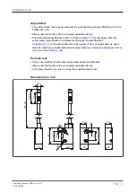
Safety switches and actuators must be positioned so that they are secured against a
change of position.

}

The safety switch and actuator should only be secured using screws and nuts made of
non-magnetic material (e.g. brass or stainless steel).

}

Avoid the risk of damages from foreseeable external influences by attaching the safety
switch and actuator. If necessary, safety switch and actuator have to be protected.

INFORMATION

Protect the actuator from unauthorised removal (e.g. via a screw lock or
concealed installation) and from contamination.

}

Prevent self-loosening of the fastening elements of safety switch and actuator.

}

The fastening of safety switch and actuator has to be sufficiently stable to ensure the
proper operation of the safety switch and the actuator.

}

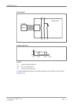
The distance between two safety switches must be maintained (see 

Technical

details [

 19]

).

}

Safety switches and actuators

– Should be kept away from iron swarf

– Should not be exposed to strong magnetic fields

}

Prevent the safety switch and actuator being exposed to heavy shock or vibration.

}

Make sure that the safety switch and actuator cannot be used as an end stop.

}

Circumvention of the safety switch in a reasonably foreseeable manner must be preven-
ted.

}

Please note the installation measures in accordance with EN ISO 14119 for a proximity
switch type 4 with coding level Low.

}

Alignment errors of the guard must not adversely affect the safety function of the guard.

Содержание PSEN ma1.4n-51

Страница 1: ...PSEN ma1 4n 51 Operating Manual 22131 EN 06 PSEN sensor technology...

Страница 2: ...nta tion will be gratefully received Source code from third party manufacturers or open source software has been used for some components The relevant licence information is available on the Internet...

Страница 3: ...ty 6 Disposal 6 For your safety 6 Unit features 7 Function description 7 Block diagram 8 Operating distances 8 Lateral and vertical offset 9 Wiring 10 Pin assignment 10 Requirements and connection to...

Страница 4: ...particularly important is identified as follows DANGER This warning must be heeded It warns of a hazardous situation that poses an immediate threat of serious injury and death and indicates preventive...

Страница 5: ...he product outside the technical details see Technical details 19 NOTICE EMC compliant electrical installation The product is designed for use in an industrial environment The product may cause interf...

Страница 6: ...anty and liability will be rendered invalid if The product was used contrary to the purpose for which it is intended Damage can be attributed to not having followed the guidelines in the manual Operat...

Страница 7: ...tor see Technical details 19 Design Safety switch with square design Actuator with square design PSEN ma1 4 03 Actuator with square design PSEN ma1 4 10 Operation Magnetic Switching voltage 24 VDC LED...

Страница 8: ...4 5 Actuator Safety switch Magnet Operating distances Sao So Sr Sar mm Somin On Off Legend Sao Assured operating distance Somin Min operating distance Sar Assured release distance The offset independ...

Страница 9: ...Lateral offset 0 1 2 3 4 0 3 0 3 0 2 5 1 5 1 0 1 3 0 2 5 2 0 0 5 2 2 5 1 5 1 0 3 1 5 0 5 4 0 5 The stated values are valid at a temperature of 20 C Actuator PSEN ma1 4 10 Assured operating distance S...

Страница 10: ...ssioning On evaluation devices with DC supply voltage Overall cable resistance 15 Ohms per channel On evaluation devices with AC supply voltage Overall cable resistance 25 Ohms per channel For details...

Страница 11: ...PNOZ Ex PNOZmulti for safety gate monitoring Configure the switch in the PNOZmulti Configurator with switch type 3 PSS for safety gate monitoring with standard function block SB064 SB066 or FS_Safety...

Страница 12: ...he risk time is made up of the reaction time of the sensor see Technical details 19 and the processing and delay times of the evaluation device s operating manual for the relevant evaluation device PS...

Страница 13: ...ff 1 2 3 4 5 GND PSENmag 1 2 3 4 5 PLC PSENmag Connecting the auxiliary contact to an eval uation device Connecting the auxiliary contact to a PLC Installation The unit can be installed in any positio...

Страница 14: ...nal influences by attaching the safety switch and actuator If necessary safety switch and actuator have to be protected INFORMATION Protect the actuator from unauthorised removal e g via a screw lock...

Страница 15: ...e screws Attach the screws for the actuator maintaining the distance between the screw head and the plate ca 3 6 mm 4 Align actuator to sensor INFORMATION The inscribed area on the actuator sensing fa...

Страница 16: ...PSEN ma1 4n 51 Operating Manual PSEN ma1 4n 51 22131 EN 06 16 1 2 3 4 5 6 7 8 9 10 11 INFORMATION Seals 1 2 3 meet the requirements of UL 94 V0 seal 4 does not meet UL requirements...

Страница 17: ...e unused mounting holes on the plate using seal 2 see Diagram 17 3 Slide the actuator on to the screws 4 Align actuator and tighten screws with max 0 8 Nm 5 Close used mounting holes using seal 1 or 4...

Страница 18: ...are installed according to the specifications Installation 14 Operating distances may deviate if other arrangements are used Note the maximum permitted lateral and vertical offset see Operating dista...

Страница 19: ...ng voltage 24 V 24 V Internal resistance 10 Ohm 10 Ohm Max switching current safety con tacts 0 2 A 0 2 A Max breaking capacity safety con tacts 5 W 5 W Max switching current auxiliary contacts 10 mA...

Страница 20: ...een safety switches 50 mm 50 mm Sensor flush installation in accord ance with EN 60947 5 2 Yes follow installation guidelines Yes follow installation guidelines Connection type M12 5 pin male connecto...

Страница 21: ...ety switch actu ator with assured operating distance 3 mm 5 pin M12 connector 506 341 PSEN ma1 4n 51 PSEN ma1 4 10mm 1unit Magnetic safety switch actu ator with assured operating distance 10 mm 5 pin...

Страница 22: ...10 m 380 214 30 m 380 215 Input module Product type Features Order No PDP67 F 8DI ION Decentralised input module IP67 for PNOZmulti 773 600 EC declaration of conformity This product these products me...

Страница 23: ...0XXXX en 0X 2021 01 Printed in Germany Pilz GmbH Co KG 2021 Support Technical support is available from Pilz round the clock Pilz develops environmentally friendly products using ecological materials...

Отзывы: