Commissioning
Operating Manual PNOZ mm0.1p
1002101-EN-04
20
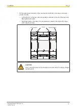
CAUTION!
Do not connect or disconnect expansion modules and terminators during
operation.
6.2.3.1
Load project from chip card
Procedure:
}
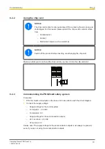
Insert the chip card containing the current project into the card slot on the base unit.
}
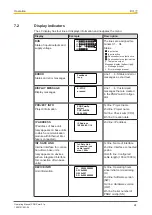
Switch on the supply voltage. The LC display shows the project name, CRC sum and
the date the project was created. Please check this information.
}
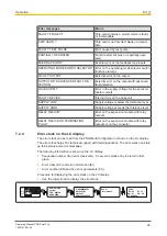
Load the project by pressing the rotary knob. For the project to be downloaded, the
rotary knob must be held down for between 3 and 8 seconds. Once the project has
been successfully downloaded, the status of the inputs and outputs will be shown on
the display.
6.2.3.2
Load project via USB port
Procedure:
}
Insert a chip card into the card slot on the base unit.
}
Connect the computer containing the PNOZmulti Configurator to the base unit via the
USB port.
}
Switch on the supply voltage.
}
Download the project (see PNOZmulti Configurator's online help).
}
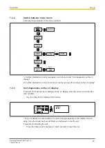
Once the project has been successfully downloaded, the status of the inputs and out-
puts and the supply voltage will be shown on the display. The "RUN" LED will be lit.
6.2.4
Connection
Supply voltage
AC
DC
For the safety system
A1
+ 24 V DC
A2
0 V
For the semiconductor outputs
Must always be present, even if
the semiconductor outputs are not
used
24 V
+ 24 V DC
0 V
0 V


