Operating Manual PMCenergy SD
1004547-EN-01
Commissioning
En
gl
is
h
20
The commissioning
procedure
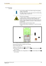
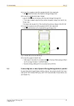
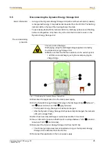
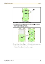
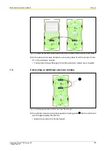
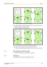
Fig. 7: Connecting terminals on the bottom of the housing
⌧
Determine the polarity of the DC link connections.
⌧
De-energise the DC link.
⌧
Make sure that there is no voltage on the DC link.
⌧
Remove the discharge bridge
between "–DC"
(black terminal) and "BR"
(grey terminal).
⌧
Make sure that there is no voltage between "–DC"
(black terminal) and "+DC"
(red terminal).
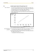
This procedure applies for "automatic setting of the operating
voltage on the DC link".
The brake resistor line is not connected in case for "fixed setting
of operating voltage on the DC link".
There is a risk of damage.
If a brake resistor is installed in the application, due to the the
parallel connection with the brake resistor installed in the
Dynamic Energy Storage Unit the current through the two resis
-
tors may become excessive and destroy the brake transistor in
the application.
⌧
See the data sheet for the brake resistor.
⌧
If necessary, modify your application or consult the manufac
-
turer.

