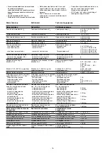
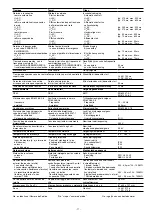
Pilz 19894-6NL-06 Скачать руководство пользователя страница 7

- 7 -

Rückfallverzögerung

bei Not-Halt
bei Netzausfall
U

B

 AC:

U

B

 DC:

Wiederbereitschaftszeit bei max.
Schaltfrequenz 1/s

nach Not-Halt
nach Netzausfall

Gleichzeitigkeit

Wartezeit bei überwachtem Start

Min. Startimpulsdauer bei
überwachtem Start

Überbrückung bei
Spannungseinbrüchen

Umweltdaten

EMV

Schwingungen nach EN 60068-2-6

Frequenz
Amplitude

Klimabeanspruchung

Luft- und Kriechstrecken nach
EN 60947-1

Verschmutzungsgrad
Überspannungskategorie

Bemessungsisolationsspannung

Bemessungsstoßspannungs-
festigkeit

Umgebungstemperatur

Lagertemperatur

Schutzart

Einbauraum (z. B. Schaltschrank)
Gehäuse
Klemmenbereich

Mechanische Daten

Gehäusematerial

Gehäuse
Front

Querschnitt des Außenleiters
(Schraubklemmen)

1 Leiter, flexibel
2 Leiter gleichen Querschnitts, fle-
xibel mit Aderendhülse, ohne
Kunststoffhülse
flexibel ohne Aderendhülse oder
mit TWIN-Aderendhülse

Anzugsdrehmoment für
Schraubklemmen

Abmessungen H x B x T

Gewicht

Delay-on de-energisation

With E-STOP
With power failure
U

B

 AC:

U

B

 DC:

Recovery time at max. switching
frequency 1/s

After E-STOP
After power failure

Simultaneity

Waiting period on monitored reset

Min. start pulse duration with a
monitored reset

Supply interruption before de-
energisation

Environmental data

EMC

Vibration in accordance with
EN 60068-2-6

Frequency
Amplitude

Climatic suitability

Airgap creepage in accordance with
EN 60947-1

Pollution degree
Overvoltage category

Rated insulation voltage

Rated impulse withstand voltage

Ambient temperature

Storage temperature

Protection type

Mounting area (e.g. control cabinet)
Housing
Terminals

Mechanical data

Housing material

Housing
Front

Cable cross section
(screw terminals)

1 core flexible
2 cores of the same cross section,
flexible with crimp connector,
without insulating sleeve
flexible without crimp  connector or
with TWIN  crimp connector

Torque setting for screw terminals

Dimensions H x W x D

Weight

Temporisation à la retombée

en cas d’arrêt d’urgence
en cas de coupure d’alimentation
U

B

 AC:

U

B

 DC:

Temps de remise en service en cas de
fréquence de commutation max. 1/s

après un d’arrêt d’urgence
après une coupure d’alimentation

Désynchronisme

Temps d’attente en cas d’un
démarrage surveillé

Durée minimale de l'impulsion pour
un réarmement auto-contrôlé

Tenue aux micro-coupures

Données sur l'environnement

CEM

Vibrations selon EN 60068-2-6

Fréquence
Amplitude

Sollicitations climatiques

Cheminement et claquage
selon EN 60947-1

Niveau d'encrassement
Catégorie de surtensions

Tension assignée d'isolement

Tension assignée de tenue
aux chocs

Température d’utilisation

Température de stockage

Indice de protection

Lieu d’implantation (p. ex. armoire)
Boîtier
Borniers

Données mécaniques

Matériau du boîtier

Boîtier
Face avant

Capacité de raccordement maximale
(bornes à vis)

1 conducteur souple
2 conducteurs de même section,
souples avec embout, sans
chapeau plastique
souples sans embout ou avec
embout TWIN

Couple de serrage pour les bornes
à vis

Dimensions H x P x L

Poids

typ. 15 ms, max. 30 ms

typ. 55 ms, max. 80 ms
typ. 50 ms, max. 70 ms

50 ms
100 ms

U

B

 AC: 150 ms

U

B

 DC: 250 ms

30 ms

20 ms

EN 60947-5-1,
EN 61000-6-2

10 ... 55 Hz
0,35 mm

EN 60068-2-78

2
III / II

250 V

4,0 kV

-10 ... +55 °C

-40 ... +85 °C

IP54
IP40
IP20

PPO UL 94 V0
ABS UL 94 V0

0,20 ... 4,0 mm

2

, 24 - 10 AWG

0,20 ... 2,5 mm

2

, 24 - 14 AWG

0,20 ... 2,5 mm

2

, 24 - 14 AWG

0,6 Nm

87 x 45 x 121 mm

U

B

 AC: 370 g

U

B

 DC: 270 g

No. ist gleichbedeutend mit Bestell-Nr.

No. stands for order number.

No. correspond à la référence du produit.

Содержание 19894-6NL-06

Страница 1: ...pplication The safety relay provides a safety related interruption of a safety circuit The safety relay meets the requirements of EN 60947 5 1 EN 60204 1 and VDE 0113 1 and may be used in applications...

Страница 2: ...operation with short circuit detection Redundant input circuit Earth faults in the emergency stop circuit and shorts across the Emergency Stop push button are also detected Automatic reset The unit is...

Страница 3: ...ut circuit Rlmax Rl km Imax Rlmax Max Total cable resistance Input circuit Rl km Cable resistance km Important for short circuit detection As the function for detecting shorts across the inputs is not...

Страница 4: ...and the auxiliary contact 41 42 closes The status indicators go out Reactivation Close the input circuit For manual reset without monitoring press the button between S33 S34 For manual rest with monit...

Страница 5: ...poussoir de validation S52 S34 S33 S11 S11 S22 S12 S21 S1 S2 S3 Y36 Y37 S52 S34 S33 S12 S11 S22 S12 S21 S1 S3 Y36 Y37 S11 S52 S12 S11 S22 S21 Y36 Y37 S34 S33 S3 Fehler St rungen Erdschluss Betrieb mi...

Страница 6: ...tact fuse protection in accordance with EN 60947 5 1 IK 1 kA Blow out fusequick Blow out fuseslow Safety cut out Characteristic Max overall cable resistance Rlmax input circuits Single channel DC Sing...

Страница 7: ...t Cable cross section screw terminals 1 core flexible 2 cores of the same cross section flexible with crimp connector without insulating sleeve flexible without crimp connector or with TWIN crimp conn...

Страница 8: ...m ssen bei der Berechnung der Sicherheitskennwerte ber cksichtigt werden INFO Die SIL PL Werte einer Sicherheits funktion sind nicht identisch mit den SIL PL Werten der verwendeten Ger te und k nnen...

Страница 9: ...allen Ausgangskontakten f r eine ausreichende Funkenl schung sorgen Bei kapazitiven Lasten sind eventuell auftretende Strom spitzen zu beachten Bei DC Sch tzen Freilaufdioden zur Funkenl schung einse...

Страница 10: ...mm Dimensions in mm Dimensions en mm 121 4 76 75 2 95 87 3 42 45 1 77 EG Konformit tserkl rung Diese s Produkt e erf llen die Anforderun gen der Richtlinie 2006 42 EG ber Maschinen des europ ischen Pa...

Страница 11: ...ci n orientada a la seguridad de un circuito de corriente de seguridad El dispositivo de seguridad cumple los requisitos de las normas EN 60947 5 1 EN 60204 1 e VDE 0113 1 y puede utilizarse en aplica...

Страница 12: ...cador de estado CH 1 y CH 2 se apaga Los contactos de seguridad 13 14 23 24 33 34 se abren por redundancia el contacto auxiliar 41 42 se cierra Aislamiento respecto del rea no marcada y de los contact...

Страница 13: ...60 75 C A la hora de conectar interruptores de proximidad magnetosensibles basados en contactos Reed prestar atenci n a que el pico m x de corriente de conexi n en el circuito de entrada no sobrecarg...

Страница 14: ...Puentear S11 S52 Conectar el contacto normalmente cerrado del elemento disparador en S11 S12 y S21 S22 Circuito de realimentaci n Puentear Y1 Y2 o conectar los contactos normalmente cerrados conmutado...

Страница 15: ...S12 S11 S22 S12 S21 S1 S3 Y36 Y37 S11 S52 S12 S11 S22 S21 Y36 Y37 S34 S33 S3 Fig 4 Circuito de entrada bicanal sin detecci n de corto circuito transversal rearme supervisado Circuito di ingresso bican...

Страница 16: ...a conduttore totale max Rlmax circuiti di ingresso a singolo canale DC a singolo canale AC bicanale senza riconoscimento di cortocircuito traversale DC bicanale senza riconoscimento di cortocircuito t...

Страница 17: ...ale di isolamento Tensione di tenuta agli urti Temperatura ambiente Temperatura di magazzinaggio Grado di protezione Spazio di montaggio p es quadro elettrico ad armadio Custodia Zona morsetti Dati me...

Страница 18: ...n cuenta todas las unidades que intervienen en una funci n de seguridad INFORMACI N Los valores SIL PL de una funci n de seguridad no son id nticos a los valores SIL PL de los dispositivos utilizados...

Страница 19: ...contactos de salida para prolongar la vida til En caso de cargas capacitivas controlar las puntas de tensi n que puedan crearse Utilizar diodos volantes para la extinci n de chispas de contactores DC...

Страница 20: ...n Germany Dimensiones en mm Dimensioni in mm Afmetingen in mm 121 4 76 75 2 95 87 3 42 45 1 77 Declaraci n CE de conformidad Estos productos cumplen los requisitos de la Directiva de M quinas 2006 42...

Отзывы: