

- 4 -
Ablauf:
• Versorgungsspannung:
- Spannung an Klemmen A1 und A2
anlegen.
- nur bei AC: Betriebserdungsklemme mit
Schutzleitersystem verbinden.
• Startkreis:
- Automatischer Start: S33-S34 und Y36-
Y37 brücken.
- Manueller Start mit Überwachung:
Taster an S33-S34 anschließen (Y36-
Y37 offen).
- Manueller Start ohne Überwachung:
Taster an S33-S34 anschließen, Y36-
Y37 brücken.
• Eingangskreis:
- Einkanalig: S12-S52 und S21-S22
brücken. Öffnerkontakt von Auslöse-
element an S11 und S12 anschließen.
- Zweikanalig ohne Querschluss-
erkennung: S21-S22 brücken.
Öffnerkontakt von Auslöseelement an
S11-S12 und S11-S52 anschließen.
- Zweikanalig mit Querschluss-
erkennung: S11-S52 brücken.
Öffnerkontakt von Auslöseelement an
S11-S12 und S21-S22 anschließen.
• Rückführkreis: Y1-Y2 brücken oder in
Reihe geschaltete Öffnerkontakte der
externen Schütze anschließen.
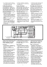
Wenn die Versorgungsspannung eingeschal-
tet und die Startbedingung erfüllt ist, sind die
Sicherheitskontakte geschlossen und der
Hilfskontakt 41-42 ist geöffnet. Die Statusan-
zeige "CH.1", "CH. 2" für Kanal 1 und Kanal 2
leuchtet. Das Gerät ist betriebsbereit.
Wenn der Eingangskreis geöffnet wird, öffnen
die Sicherheitskontakte 13-14, 23-24, 33-34
und der Hilfskontakt 41-42 schließt. Die
Statusanzeige "CH.1", "CH. 2" erlischt.
Wieder aktivieren
• Eingangskreis schließen.
• Bei manuellem Start ohne Überwachung
Taster zwischen S33 und S34 betätigen.
• Bei manuellem Start mit Überwachung
Taster nach dem Schließen des Ein-
gangskreises und nach Ablauf der
Wartezeit betätigen.
Die Statusanzeigen leuchten wieder, die
Sicherheitskontakte sind geschlossen.
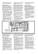
Anwendung
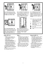
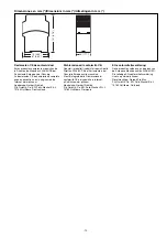
Fig. 2 bis Fig. 9 sind Anschlussbeispiele.
Beachten Sie bei Fig. 2: Das Gerät startet
bei Spannungsausfall und -wiederkehr
automatisch. Verhindern Sie einen unerwar-
teten Wiederanlauf durch externe
Schaltungsmaßnahmen.
To operate:
• Supply voltage:
- Apply voltage to A1 and A2.
- AC only: Connect the operating earth
terminal with the ground earth.
• Reset circuit:
- Automatic reset: Link S33-S34
and
Y36-Y37.
- Manual reset with monitoring: Connect
button to S33-S34 (Y36-Y37 open).
- Manual reset without monitoring:
Connect button to S33-S34, Y36-Y37
linked.
• Input circuit:
- Single-channel: Link S12-S52 and S21-
S22. Connect N/C contact from safety
switch (e.g. emergency stop) to S12
and S11.
- Dual-channel, without short circuit
detection: Link S21-S22. Connect N/C
contact from safety switch (e.g.
emergency stop) to S11-S12 and S11-
S52
- Dual-channel, with short circuit
detection: Link S11-S52. Connect N/C
contact from safety switch to S11-S12
and S21-S22
• Feedback control loop: Link Y1-Y2 or
connect external relays/contactors in
series
If the operating voltage is applied and all
conditions met, the safety contacts are
closed and the auxiliary contact (41-42) is
open. The status indicators "CH.1"and
"CH.2"
are illuminated. The unit is ready for
operation.
If the input circuit is opened, the safety
contacts 13-14, 23-24, 33-34 open and the
auxiliary contact 41-42 closes. The status
indicators go out.
Reactivation
• Close the input circuit.
• For manual reset without monitoring,
press the button between S33-S34.
• For manual rest with monitoring, press the
button after the input circuit has closed and
the waiting time has elapsed.
The status indicators light up again, the
safety contacts are closed.
Application
In Fig. 2...Fig. 9 are connection examples.
Please note for Fig. 2: the device starts
automatically after loss of power. You should
prevent an unintended start-up by using
external circuitry measures.
Utilisation
Les figures 2 à 9 représentent les différents
câblages possibles du PNOZ X4.
Dans le cas de la figure 2, l’appareil se
réarme automatiquement après une coupure
et une remise sous tension. Evitez tout
risque de redémarrage par un câblage
externe approprié.
Mise en oeuvre :
• Tension d’alimentation
- amener la tension d’alimentation sur A1
et A2.
- AC seulement: relier la borne terre
• Circuit de réarmement:
- réarmement automatique: pontage des
bornes S33-S34 et Y36-Y37
- réarmement manuel auto-côntrolé:
câblage d'un poussoir sur S33-S34
(Y36-Y37 ouvert)
- réarmement manuel sans côntrole:
câblage d'un poussoir sur S33-S34,
pontage des bornes Y36-Y37.
• Circuits d’entrée:
- Commande par 1 canal : câblage du
contact à ouverture entre S11-S12,
pontage entre S21-S52 et S21-S22
- Commande par 2 canaux sans détection
des courts-circuits : câblage des
contacts à ouverture entre S11-S12,
S11-S52, pontage entre S21-S22
- Commande par 2 canaux avec
détection des courts-circuits : câblage
des contacts à ouverture entre S11-
S12, S21-S22, pontage entre S11-S52
• Boucle de retour:
Ponter les bornes Y1-Y2 ou câbler en
série les contacts repos des contacteurs
externes
Dès que la tension d'alimentation et les
conditions de réarmement sont présentes,
les contacts de sécurité se ferment et le
contact d’information 41-42 s’ouvre. Les
LEDs "CH.1" et "CH.2" sont allumées.
L’appareil est prêt à fonctionner.
Si le circuit d’entrée est ouvert, les contacts
de sécurité13-14, 23-24, 33-34 retombent et
le contact d’information 41-42 se ferme. Les
LEDs s’éteignent.
Remise en route :
• fermer les circuits d’entrée
• Réarmement manuel : action sur le
poussoir raccordé sur S33-S34
• Réarmement manuel auto-contrôlé :
action sur BP après fermeture des circuits
d’entrées et écoulement du temps
d’attente.
Les affichages d'état s'allument à nouveau.
Les contacts de sécurité sont fermées.
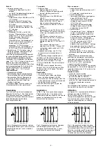
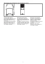
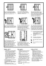
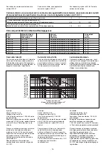
Fig. 4: Eingangskreis zweikanalig, ohne
Querschlusserkennung, überwachter Start/
Two-channel input circuit, no short circuit
detection, monitored reset/Commande par 2
canaux, sans détection de court-circuit,
surveillance du poussoir de validation
Fig. 3: Eingangskreis einkanalig, überwach-
ter Start/Single-channel input circuit,
monitored reset/Commande par 1 canal,
surveillance du poussoir de validation
Fig. 2: Eingangskreis einkanalig, automat.
Start/Single-channel input circuit, automatic
reset/Commande par 1 canal, validation
automatique
S11 S12
S33
S12
S34
S52
S21
S22
Y36
Y37
S1
S11 S12
S33
S12
S34
S52
S21
S22
S1
S3
Y36
Y37
S11
S12
S22
S34
S52
S33
S21
S11
S1
S3
Y36
Y37