Pilot Communications J-10 Jet 107

Flight Preparation

   Make sure you have the right model programmed into your transmitter 

   Check the direction of each surface not and also right before you take off . 

   Remember nothing wrong on the ground ever improves in the air 

   Check the air plane with the engine running and do a range check with  

   your body between you and the plane at least 150 feet. 

   Check your battery voltage after each flight, in case one servo is draining your 

battery 

   Recheck all screws ,horns and linkages for slop after your maiden fight and 

check for damage if you made a bad landing you first time 

   Have an experienced pilot fly it for you the first time if you have any doubts in 

your mind about the maiden flight 

   Take a break after you first flight and let the adrenaline burned off by bragging to 

your fellow members how good it flies 

   Fly low and at a medium speed on your first few flight 

   Listen to your engine run and have an observer with you to remember what you 

talked about during the flight or if you get into trouble . Always balance your props, 
vibration is a killer. 

   Remember nose heavy airplanes fly all the time, tail heavy airplanes fly only 

once. Be on the CG! 

   Flying two mistakes: high in the beginning and not close to people, planes or 

runways. Being a center of the runway hog does not endear you to many modelers.

Double Check

Double check that all screws are installed, all components tightly secured, batteries 
and or fuel tank are full, all surfaces are working in the correct directions, balance is 
correct and range test passed before performing your maiden flight

.

WE WISH YOU A SUCCESSFUL MAIDEN AND MANY HAPPY FLIGHTS WITH 

YOUR NEW MODEL

Tony Tan, Pilot-RC


Содержание J-10 Jet 107"

Страница 1: ...J 10 Jet 107 USER MANUAL WINGSPAN 1650mm LENGTH 2700mm...

Страница 2: ...ature requires previous experience and competence to an experienced level This plane is not for a beginner 4 If you are in doubt have an experienced pilot at hand Diligent practicing and correct guida...

Страница 3: ...tents Some contents like fuel tank etc has already installed in fuselage Carbon tube The outer diameter is 35mm the wall thickness is 1 5mm and the length is 710 mm Landing gear module optional Landin...

Страница 4: ...Tapping screws Metric Allen Wrench Push rot wrench V teeth steel wire Push rot Wring clamp Gasket Battery bandage Oil nipple suit Extension cord Crowbar Some of accessories like screw cord etc isn t...

Страница 5: ...ilot Futaba aluminum alloy 0 8 2 Pilot Futaba aluminum alloy 1 2 3 Pilot Futaba aluminum alloy 1 6 2 Install kit contents Other Accessories Need To Complete Epoxy Adhesives Cyanocrylate adhesives X Ac...

Страница 6: ...nding gear assembly 1 Install the servo to the nose landing gear 2 Install the servo arm and the push rod Adjust it to make sure the plane can go straight approx You still can adjust by radio after in...

Страница 7: ...mounting and adjust it to the correct position then mark the 4 mounting screws hole Front landing gear assembly 4 Before you drilling the mounting screws hole please make sure there is nothing to get...

Страница 8: ...1 Use M4 14 screw to lock on the reserved space and use special fixed aluminum sheet to connect left and right for reinforcement Landing gear assembly main...

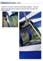
Страница 9: ...Landing gear assembly main 2 Check the main landing gear for interference...

Страница 10: ...Wing Servo Assembly The control horns are pre installed at the factory ready for use screw the servo to the servo plate then install the servo arm on to the servo making sure that this is centred...

Страница 11: ...Rudder Servo Assembly 1 Insert the servo into the precut servo mount screw the servo in place and then install the servo arm on to the servo making sure that this is centred...

Страница 12: ...sembly 2 Next is the elevators as follows the servo is fixed put in the servo to the precut slot in the elevator screw the servo in place and then install the servo arm on to the servo making sure tha...

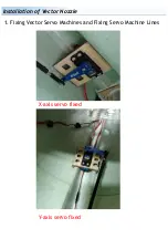
Страница 13: ...Installation of Vector Nozzle...

Страница 14: ...Distance of vector rotation Installation of engine and vector is completed Distance between Rear End of Engine and Vector Leading Edge 15mm...

Страница 15: ...Installation of Vector Nozzle 1 Fixing Vector Servo Machines and Fixing Servo Machine Lines X axis servo fixed Y axis servo fixed...

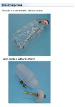
Страница 16: ...Tank Arrangement The 106 J10 use PilotRC 5000ml oil tank Anti bubble oiltank 250ml Fuel vent...

Страница 17: ...t later and stick the Velcro stick on the tank support frame Also you need stick the Velcro stick on the fuel tank to arrange the tank on the support frame use Velcro stick tape to straining the tank...

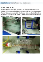
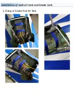
Страница 18: ...Installation of main oil tank and Smoke tank 2 Fixing of Smoke Pull Oil Tank...

Страница 19: ...Installation position of UAT and smoke pump...

Страница 20: ...Installation of each controller On top of the nose gear...

Страница 21: ...the root of the wing Aileron 21mm Rudder 22mm Elevator 21mm Vector setting X axis 19mm Y axis 9mm 1 Setting of Rudder Surface in 3D Flight 2 Setting of Control Surface in Airline Flight Aileron 40mm R...

Страница 22: ...and let the adrenaline burned off by bragging to your fellow members how good it flies Fly low and at a medium speed on your first few flight Listen to your engine run and have an observer with you t...

Страница 23: ...34 Chengnan Er Road Zhongshan city 528455 Guangdong Province China Web www pilot rc com Email pilot rc 139 com info pilot rc com Tel 86 760 88781293 FAX 86 760 88780293 Zhongshan Pilot Model Aircraft...

Отзывы: