background image

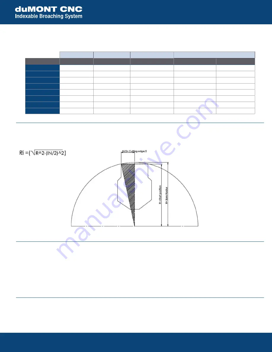
PROCESSING START TANGENT ARC CALCULATION FOR INTERNAL

Before starting processing, always consider the tangent arc distance to avoid chipping or breaking the insert (figure 6).

FIGURE 6

Motorized Slotter

15 Merrigan Way | South Deerfield, MA 01373 | 413-350-5200 | PilotPrecision.com | ISO 9001 : 2015

CUTTING PARAMETERS

For each material, based on our experience, the recommended parameters are:

35 mm Ram Stroke

50 mm Ram Stroke

65 mm Ram Stroke

RPM = cut speed ÷ (ram stroke x 2)

Insert Width

Insert Width

Insert Width

 Cutting speed

Cut per Stroke Min / Max

Aluminum

5/8 in.

5/8 in.

5/8 in.

1496 in./min.

.0023/.0059 in.

Soft steel

9/16 in.

9/16 in.

9/16 in.

1299 in./min.

.0015/.0027 in.

Cast iron

9/16 in

9/16 in.

1/2 in.

1102 in./min.

.0015/.0027 in.

Common steel

9/16 in

9/16 in.

1/2 in

1181 in./min.

.0011/.0019 in.

Hardened steel

1/2 in.

1/2 in.

3/8 in.

984 in./min.

.0007/.0015 in.

Stainless steel

1/2 in

1/2 in.

3/8 in.

984 in./min.

.0007/0015 in.

Plastic

3/4 in.

3/4 in.

3/4 in.

1574 in./min.

.0027/0059 in.

Bronze-Brass

9/16 in.

1/2 in.

1/2 in.

1181 in./min.

.0011/.0023 in.

PROGRAMMING BEST PRACTICES

CAUTION: Consider tangent arc at the start of processing, under the lathing diameter (figure 6).

• 

Set feed to units per revolution.

• 

Set speed to revolutions per minute.

• 

For internal features, use clockwise live spindle direction; for external features use counterclockwise live spindle direction.

• 

Spindle RPM = SurfaceSpeed / (StrokeLength x 2)*

*Be sure to convert units to match if necessary

RETRACT DURING THE RETURN STROKE

During the return phase, the tool detaches from the processed surface by 0.25 mm. This movement is essential to preserve the integrity of 

the insert. This is automatic and a function of the elliptical path referenced on page 1.

Содержание duMONT CNC

Страница 1: ...e motorized slotter and are used to grease after about 10 hours of use meaning the effective operating time of the tool see example of calculation for greasing COOLANT FITTING HOLE FOR COOLANT SUPPLY All of the tools feature holes for the supply of coolant The internal supply is recommended more than the external supply and allows the lubricant to be directed to the cutting area 15 Merrigan Way So...

Страница 2: ...the out stroke to ensure the elliptical motion does not interfere INDICATOR FIGURE 2 SETUP For VDI style turrets attach the slotter onto the interface and tighten the 4 attachment screws holding the slotter onto the interface then install the unit onto the machine For BMT style turrets remove the slotter from the interface by loosening the 4 attachment screws and removing the slotter from the inte...

Страница 3: ...se the motorized device the rotary motion drive shaft must be properly fixed to the motorized device by means of an Allen screw To implement the procedure for the flange machine change follow the steps below Tool disassembly Removal of adjustment snib fixed by M3 screw Y adjustment rod removal from the back Cap removal from cover Allen screw removal with key Shaft extraction from cam Caution when ...

Страница 4: ...16 in 1 2 in 1181 in min 0011 0019 in Hardened steel 1 2 in 1 2 in 3 8 in 984 in min 0007 0015 in Stainless steel 1 2 in 1 2 in 3 8 in 984 in min 0007 0015 in Plastic 3 4 in 3 4 in 3 4 in 1574 in min 0027 0059 in Bronze Brass 9 16 in 1 2 in 1 2 in 1181 in min 0011 0023 in PROGRAMMING BEST PRACTICES CAUTION Consider tangent arc at the start of processing under the lathing diameter figure 6 Set feed...

Страница 5: ...arts subject to wear such as bearings gaskets etc To keep your Motorized Slotter working at maximum efficiency we give you the option of using our DIY Rebuild Kit or send us your equipment to repair at our facility For more information or to request a quote visit pilotprecision com contact 15 Merrigan Way South Deerfield MA 01373 413 350 5200 PilotPrecision com ISO 9001 2015 Motorized Slotter MAIN...

Отзывы: