


TD250 V8 Manual
14
Rev 2, 31-09-2020
15
Driving Piezoelectric Tubes
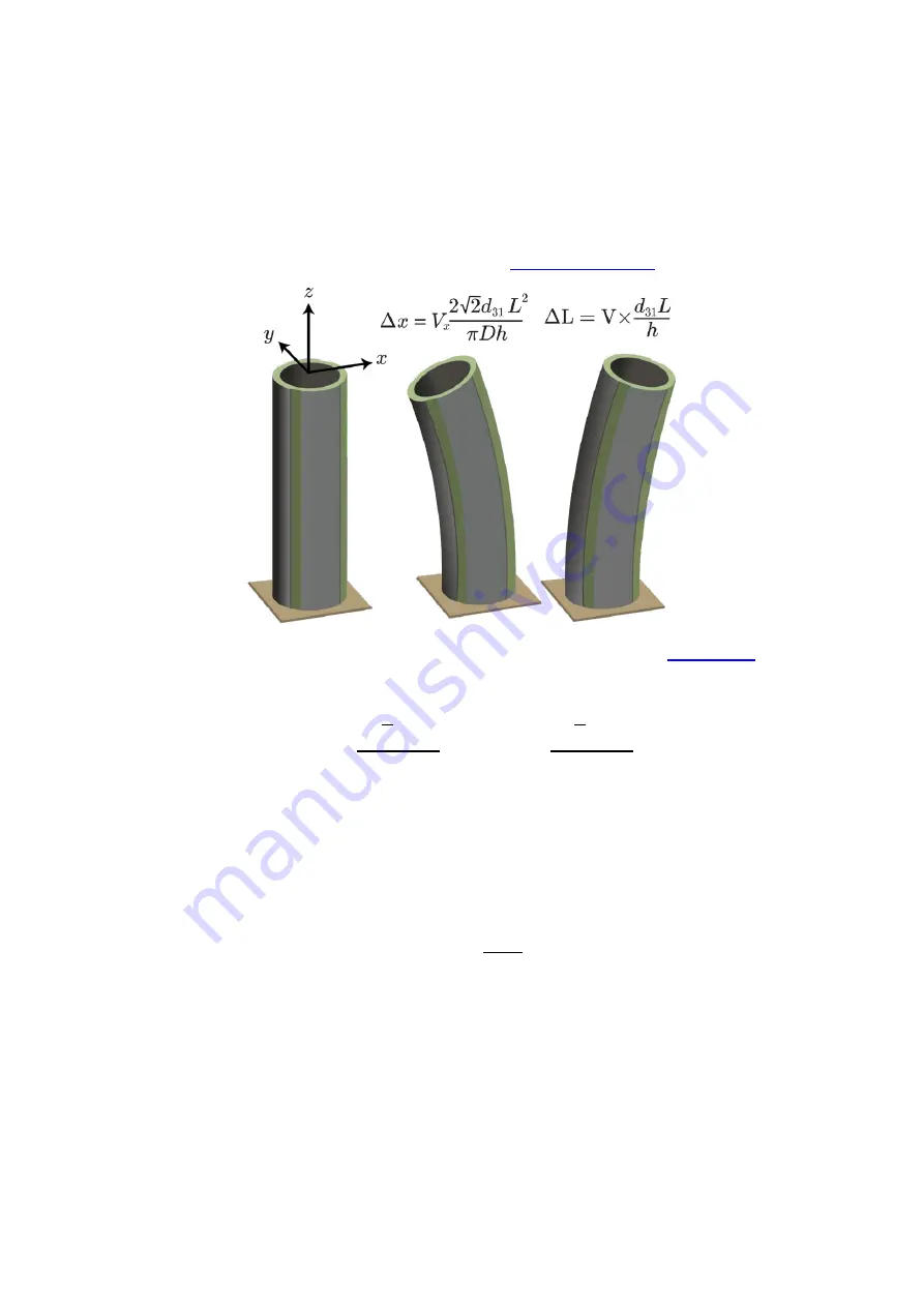
Piezoelectric tube scanners are thin cylinders of radially poled piezoelectric material with four
external electrodes and a continuous internal electrode. When a voltage is applied to one of the
external electrodes, the actuator wall expands which causes a vertical contraction and a large lateral
deflection of the tube tip. A circumferential electrode can be used for vertical or radial extension and
contraction. Piezoelectric tube scanners are used extensively in scanning probe microscopes and
applications such as fibre stretching and beam scanning.
Figure 10. Piezoelectric tube with a fixed base and free end (
When the base of the tube is fixed, the tip translations
Δ𝑥
and
Δ𝑦
are approximately [1]
Δ𝑥 = 𝑉
𝑥
2√2𝑑
31
𝐿
2
𝜋𝐷ℎ
, Δ𝑦 = 𝑉
𝑦
2√2𝑑
31
𝐿
2
𝜋𝐷ℎ
where
Δ𝑥
and
Δ𝑦
are the
𝑥
and
𝑦
axis deflection,
𝑑
31
is the piezoelectric strain constant,
𝐿
is the
length of the tube,
𝐷
is the outside diameter,
ℎ
is the tube thickness, and
𝑉
𝑥
and
𝑉
𝑦
are the electrode
voltages, which are applied oppositely to either side of the tube.
The vertical elongation due to a voltage
𝑉
applied on all four quadrants is
Δ𝐿 = −𝑉
𝑑
31
𝐿
ℎ
The diameter expansion due to a voltage applied on all four quadrants or the internal electrode is
Δ𝐷 = 𝑉2𝑑
33
The expansion range in the vertical and radial directions can be doubled by driving the internal and
external electrodes with opposite voltages, so long as the maximum permissible voltage is not
exceeded.
The TD250 is optimized for driving piezoelectric tube scanners in applications that require lowest
possible electronic and mechanical noise. Although many configurations are possible, the driven
internal electrode configuration shown in Figure 11 provides the maximum X, Y and Z travel range [1].


