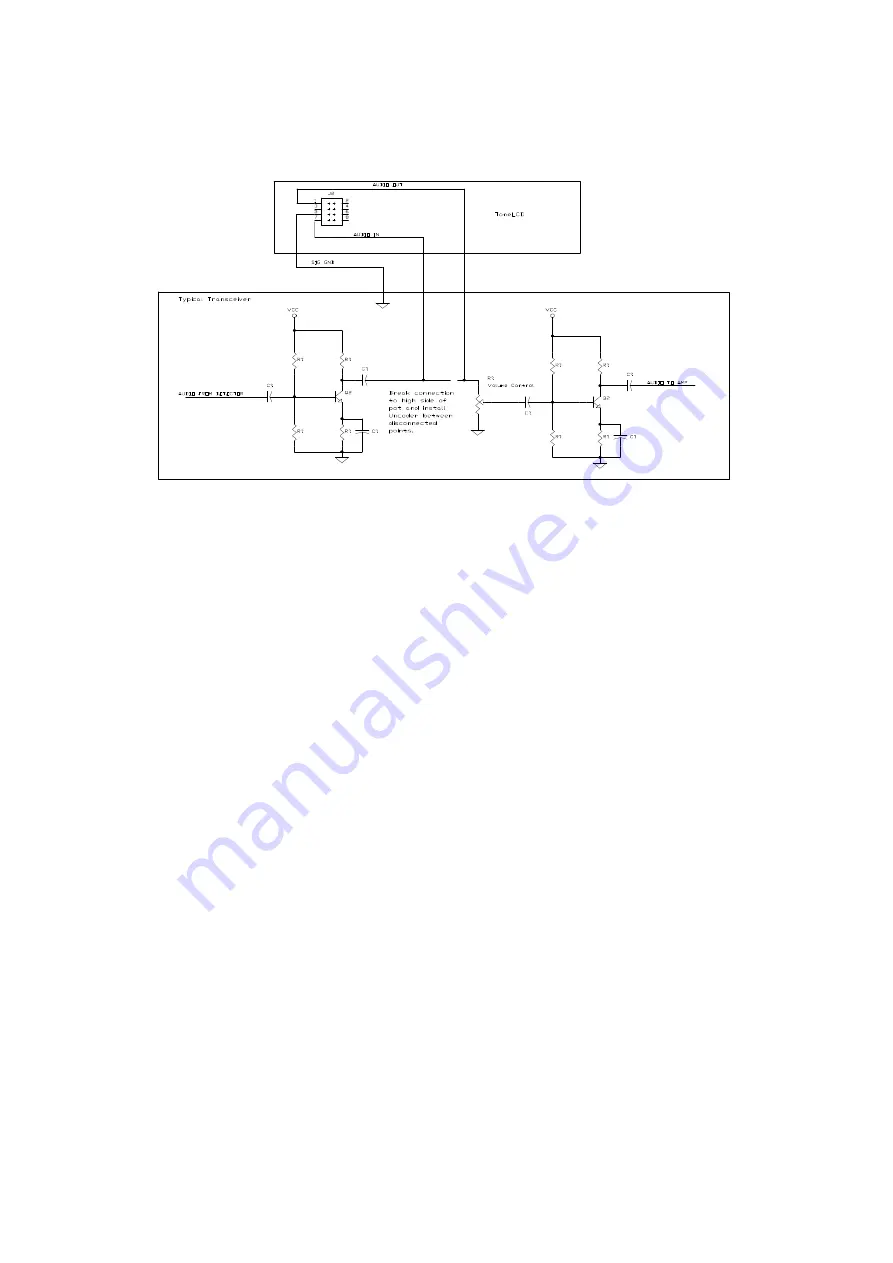
control and leave J2 pin 1 unconnected. If you do not connect the audio in
signal to the ToneLCD, the device will not be able to detect and report the
CTCSS tone being used with its FIND mode.
Fig. 1
ToneLCD
Receive Audio Connection
The tone output is available from the Uncoder on connector J2 pin 3. If your
rig has a connection point for a tone generator, you should connect the tone
out to it. Otherwise, connect J2 pin 3 to a point in the transceivers close to
the modulator and past the mic conditioning circuitry. The tone output level
from the ToneLCD can be adjusted to about 1V RMS if necessary. Often a
good point to inject the tone output is the high side of the deviation control.
If you must connect the tone output to a point in the transceiver near the mic
input you may need to install a series resistor in line with it to reduce the
tone signal level so that it won’t swamp out the modulator
The ToneLCD has an input signal, on J2 pin 6, that can be used as either a
transmit detector input or a hang up switch input. If the input is used as a
transmit detector, the CTCSS tone output will only be present when the
input line is asserted. Alternatively if you have a mic holder that is switched,
you can connect the input signal to it and when you unhook the mic the tone
squelch will be defeated allowing you to hear the channels activity. If the
input is used as a hang up, the receive audio path will be made, regardless of
the presence of a valid CTCSS audio tone, whenever the input line is
asserted. In the transmitter detector mode, P2 pin 6 should be connected to
either the PTT line on your Mic plug, the transmit indicator light or a
switched Xmit power connection. In the hang up mode, P2 pin 6 should be
connected to your mic hang up switch. Don’t worry about the polarity of the
signals; the input polarity can be switched in one of the setup menus.


