5
MT 235 – EN ed.2015 (Rev.A)
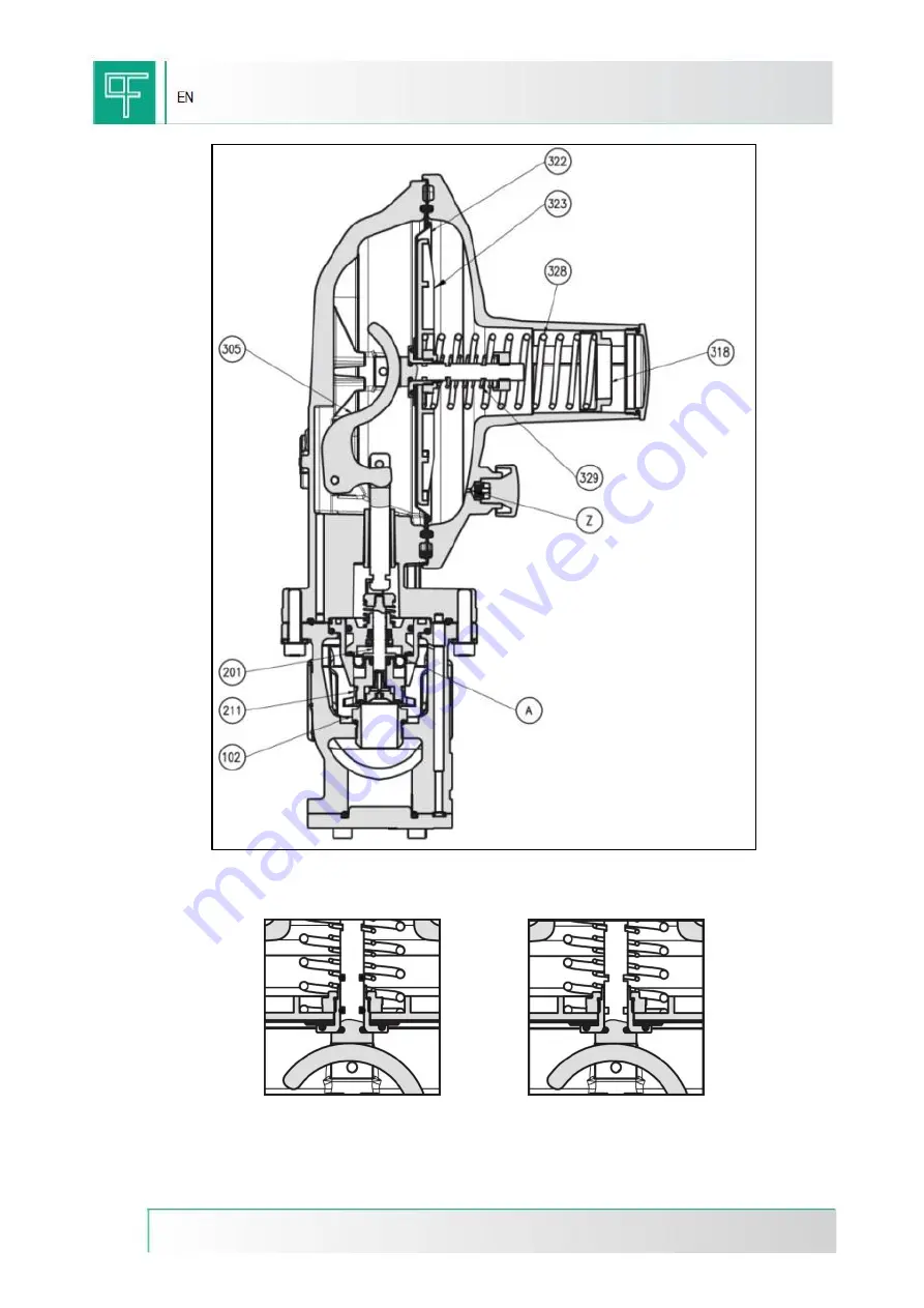
Figure 1: DIVAL 500
Figure 2: Relief version NO
Figure 3: Relief version YES
Страница 1: ...EN TECHINICAL MANUAL Pressure Regulators DIVAL500...
Страница 2: ...2 MT 235 EN ed 2015 Rev A EN DIVAL Basic version INLET PRESSURE OUTLET PRESSURE DIVAL 500...
Страница 3: ...tallation in compliance with such standards minimizes the risk of fire and the formation of potentially hazardous atmospheres The equipment is not provided with internal pressure limitation devices th...
Страница 4: ...s transmitted by the lever system 305 to the stem 201 and therefore to the obturator 211 The obturator is provided with a vulcanized rubber gasket in order to assure a perfect tightness when the reque...
Страница 5: ...5 MT 235 EN ed 2015 Rev A Figure 1 DIVAL 500 Figure 2 Relief version NO Figure 3 Relief version YES...
Страница 6: ...143BI WHITE 34 97 4 5 300 599 64470144VI PURPLE 34 100 5 600 999 64470145AR ORANGE 34 100 5 5 1000 1799 64470151BL BLUE 34 5 100 6 5 1800 2500 De external d wire Lo Length 1 4 RELIEF VALVE CALIBRATION...
Страница 7: ...accessible for performing the following maintenance operations see overall dimensions in table 2 1 the inlet and outlet pipings are on the same level and are able to support the regulator weight see t...
Страница 8: ...Rp 1 4 DIVAL500 LA 25x25 1 x1 110 255 182 185 5 161 173 Rp 1 4 Rp 1 4 DIVAL500 25x40 1 x1 1 2 130 257 55 185 5 173 Rp 1 4 DIVAL500 LA 25x40 1 x1 1 2 130 257 182 185 5 161 173 Rp 1 4 Rp 1 4 Table 2 2 W...
Страница 9: ...ges of sensors membranes shall be conveyed in compliance with the EN 12186 or EN 12279 standards In order to prevent impurities and condensation from building up in the pressure sensing tubes it is ad...
Страница 10: ...g its alignment even after the installation of the regulator 3 1 EMBEDDED SLAM SHUT VALVE LA It is a device fig 9 that immediately blocks the gas flow if due to any failures the outlet pressure reache...
Страница 11: ...e of the spring 547 This causes the movement of the shaft 535 which by means of the cam moves the touch probe 509 thus releasing the lever mechanism In this way the stem 517 is freed and the obturator...
Страница 12: ...GREY 34 42 2 8 140 179 64470116GI YELLOW 34 40 3 2 180 279 64470051BI WHITE 34 50 3 2 280 450 Tripping due to minimum pressure 64470024BI WHITE 15 45 1 3 10 59 64470038GI YELLOW 15 40 2 60 240 De ext...
Страница 13: ...ame allows the outlet pressure to reach the calibration value set for the monitor regulator For this emergency device PIETRO FIORENTINI has a solution for installations with an line monitor regulator...
Страница 14: ...subsequent discharge of a given quantity of gas As soon as the pressure falls below the calibration value the obturator returns to the closed position The control and adjustment of the relief valve t...
Страница 15: ...tions PS maximum allowable pressure that can be born under safety conditions by the device body structure Wds calibration range of the pressure regulator pilot pre reduction unit that can be obtained...
Страница 16: ...ons consisting of two lines it is recommended to commission one line at a time starting from the one with the lower calibration value i e the so called spare backup or standby line Before commissionin...
Страница 17: ...the adjustment ring nut 549 rotate it counter clockwise to decrease the tripping value trip in case of pressure increase and decrease slowly increase the auxiliary pressure and record the tripping va...
Страница 18: ...iary pressure and verify the tripping value If necessary increase the tripping value by rotating clockwise the adjustment ring nut 549 rotate it counterclockwise to decrease the tripping value For the...
Страница 19: ...losed position Open the inlet on off valve V1 Very slowly open the slam shut valve by pulling the proper bushing Partially open the relief valve 6 on the outlet piping Using the pressure gauge 5 check...
Страница 20: ...means of the suitable bushing 5 Keep the knob 1 pressed and For the safety devices tripping in case of maximum pressure slowly increase the auxiliary pressure and verify the tripping value If necessar...
Страница 21: ...ge 4 and 5 check that the outlet pressure shows the calibration value preset for the monitor regulator 1 Should this not be the case adjust the calibration by acting on the proper internal ring nut tu...
Страница 22: ...ment 6 2 ANOMALIES OF THE SLAM SHUT DEVICE LA Table 6 2 describes the possible anomalies that the slam shut device may show INCONVENIENCE POSSIBLE CAUSES INTERVENTION The blocking obturator does not c...
Страница 23: ...ed To have a set of tools as shown in table 7 5 For proper maintenance the recommended spare parts are unequivocally identified by tags indicating The SS layout drawing number of the equipment in whic...
Страница 24: ...ty status 2 Make sure that the pressure upstream and downstream of the same is zero DISASSEMBLING AND RE ASSEMBLING 7 3 REGULATOR DIVAL 500 3 Disconnect the fittings between the regulator and the down...
Страница 25: ...ction disc the membrane and the membrane support 10 By raising and lowering them check the proper functioning of the internal lever mechanisms CAUTION INTERNAL RELIEF ACTIVE theO ringmust beinthelower...
Страница 26: ...for disassembly in reverse order Before reassembling the tightness elements O rings membranes etc it is necessary to check their integrity and if necessary replace them Moreover it is recommended to...
Страница 27: ...ct the fittings between the slam shut valve and the downstream pressure sensing line 3 Remove the screws that secure the slam shut device to the body 4 Remove the slam shut device 5 Unscrew the plug a...
Страница 28: ...9 Extract the shaft assembly from the top 10 Unscrew the nut and remove the obturator To re assemble the slam shut valve follow the procedure described for disassembly in reverse order Before reassemb...
Страница 29: ...ting very slowly pull the bushing of the slam shut valve until opening only the internal bypass Then when pressure has equalized pull until the coupling is latched position 3 Check the tightness of th...
Страница 30: ...Via Enrico Fermi 8 10 36057 Arcugnano VI Tel 39 0444 968511 Fax 39 0444 960468 www fiorentini com R code generated on http qrcode littleidiot be...