


English
39
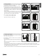
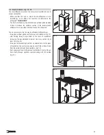
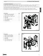
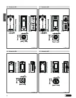
TOP - REAR flue gas outlet
IMPORTANT INFORMATION:
- Pipes with diameter
15 cm
;
- 5cm
must be deducted for each joint;
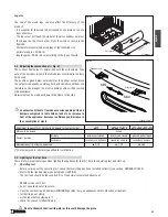
Having calculated the section of the hole for connection to the flue,
fix the trim collar and the wall connector pipe (Fig. 24).
Ensure that everything is installed in a workmanlike manner.
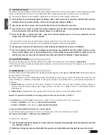
The measurements shown in the figures are approximate,
since appliance installation is envisaged in a place where
the floor is level and the wall at right angles to the floor.
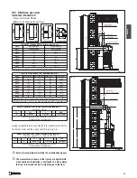
TR100
95
DT2030060-00
T100
95
DT2030256-00
T50
T50
90
DT2030201-00
24,5
24,5
C6
DT2030200-01
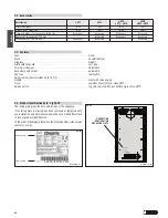
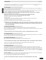
Approx. calculation of the section of vertical pipe knowing “H”.
Example: H = 80 cm
80
-
24,5
+
5
=
60,5
H
Elbow C6
Pipe joint
Pipe lenght
One 100 cm pipe
“T100”
should be cut to 60,5 cm
Cut the pipe from the spigot end
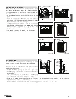
Approx. calculation of the section of horizontal pipe knowing “E”.
Example on stove e917: E = 50(cm), D = 38(cm)
50
+
38
-
24,5
+
5
=
68,5
E
D
Elbow C6
Pipe joint
Pipe lenght
One 100 cm pipe
“T100”
should be cut to 68,5 cm
Cut the pipe from the spigot end
TABLE REAR FLUE GAS OUTLET (Measurements in cm)
Model
Measurement A
Measurement B
e911
Not envisaged
Not envisaged
e912
102
29,5
e915
85
26,5
e917
93
30
e918
85
26,5
e920
102
29,5
e922
100,5
30
e923
102
29,5
Calculation of the value “B” with a minum safety distance from the rear wall of 20 cm
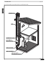
TABLE TOP FLUE GAS OUTLET (Measurements in cm)
Model
Measurement C Measurement D Measurement H Measurement F
e911
126,5
37,5
120
246,5
e912
93
37,5
120
213
e915
76,5
34,5
120
196,5
e917
83,5
38
120
203,5
e918
76,5
34,5
120
196,5
e920
93
37,5
120
213
e922
91,5
38
120
211,5
e923
93
37,5
120
213
Calculation of the value “D” with a minum safety distance from the rear wall of 20 cm
Calculation of the values “F” and “H” with a single one-metre pipe“TR100” and one elbow “C6”
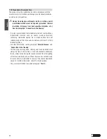
B
Wall rose
Inflammable or
heat sensitive surface
Optional connector
40 mi n.
20
20
20
F
LU
E
E
Large pipe
DT2030738-00
Fig. 25
C
F
H
40 mi n.
Inflammable or
heat sensitive surface
Wall rose
Pipes
20
20
20
F
L
U
E
E
D
DT2030739-00
Fig. 26


