PIAB KCS Series Скачать руководство пользователя страница 4


Page 4 of 30


Intended use 
The gripper is intended exclusively for handling, lifting and storing products of appropriate size, as reported in the 
agreement.  

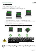
The products handled by this equipment must have the following characteristics: 

-


They must not be deformed; 

-


Have a uniform height over the entire gripping surface. Any height differences must be reported in the agreement. If 
they are not reported, Piab AB and / or Kenos will not be responsible for malfunction. 


Not intended use 
The gripper must not be used: 

-


For uses other than those established by the manufacturer or reported in this manual; 

-


In direct contact with corrosive gases, chemical products, water, vapor or in environments with droplets or splashes of 
water, oil, etc.;  

-


In explosive atmospheres; 

-


In environments subject to strong vibrations and/or impacts; 


Waste disposal  
In case of disposal of the system or non-working parts, follow these procedures: 


Provide for disposal to Authorized Bodies, in full compliance with current regulations regarding waste. 
 
Where non-

reusable and / or deemed RAEE “waste” such as

 electrical and electronic equipment are not to be given in urban 

waste collection bins. As far as the metal parts of the system are concerned, it is sufficient to subdivide the different materials 
for a correct recycling by casting. 
 
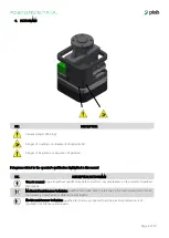
Identification data and product number 
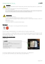
Example of label: 


Each product is identified by a label on which the reference data of the same are indelibly marked. 
For any communication with PIAB or service centers always quote these references.


Kenos Code: K-06-00083-00 
Type model product: 


KCS.Q110.N301.110.FR6.SX422.X.X.50 

Item no: 9936329 
Foam spare part no: 


9936294 

Foam spare part MP no:


Country of origin:   ITALY 

-- 29/01/2019 -- 

Содержание KCS Series

Страница 1: ...KCS SERIES ASSEMBLY MANUAL Rev 02 www piab com ...

Страница 2: ...EAS 5 3 PICTOGRAMS 6 4 R E S S APPLIED AND RESPECTED 7 5 INSTALLATION 9 6 WORKING CYCLE DETAILS 17 7 PARTS LIST 18 8 MAINTENANCE 21 9 PROBLEMS SOLUTIONS 22 10 ACCESSORIES 23 11 TECHNICAL DATA 25 12 PNEUMATIC DIAGRAM 26 13 SPARE PARTS 28 14 WARRANTIES 29 ...

Страница 3: ... malfunction Installing condensate drains or dryers prevents these malfunctions For more information see the Installation and Commissioning section Electric connection Connect the cables separately from power or high voltage lines avoiding parallel wiring or wiring in the same conduit of the same lines Control circuits that include sensors and coils may malfunction due to the noise from these othe...

Страница 4: ...nvironments subject to strong vibrations and or impacts Waste disposal In case of disposal of the system or non working parts follow these procedures Provide for disposal to Authorized Bodies in full compliance with current regulations regarding waste Where non reusable and or deemed RAEE waste such as electrical and electronic equipment are not to be given in urban waste collection bins As far as...

Страница 5: ... module described in this manual is designed for implementation in industrial systems therefore it must not be used with the conditions other than those specified The final evaluation of the safety systems to be applied for starting up the system after the assembly of the gripping module is the task of the final manufacturer of machinery It is up to the final manufacturer of machinery to report th...

Страница 6: ...PIC DESCRIPTION PICTOGRAMS Generic manual operator without specific skills able to perform only simple tasks on the orders of qualified technicians Mechanical maintenance technician qualified technician able to intervene on the mechanical parts to make the necessary adjustments maintenance and repairs Electric maintenance technician qualified technician is proposed to all the electrical interventi...

Страница 7: ...er supply 1 3 Measures of protection against mechanical hazards 1 3 1 Risk of loss of stability 1 3 2 Risk of break up during operation 1 3 3 Risks due to falling or ejected objects 1 3 4 Risks due to surfaces edges or corners 1 3 5 Risks related to combined machinery 1 3 6 Risks related to variations in operating conditions 1 3 7 Risks related to moving parts 1 3 8 Choice of protection against ri...

Страница 8: ...isk of being trapped in the machine 1 5 15 Risk of slipping tripping or falling 1 5 16 Lightning 1 6 Maintenance 1 6 1 Maintaining the Machine 1 6 2 Access to jobs and servicing points used for the maintenance 1 6 3 Isolation from sources of energy supply 1 6 4 Operator intervention 1 6 5 Cleaning of internal parts 1 7 Informations 1 7 1 Information and warnings on the machine 1 7 1 1 Information ...

Страница 9: ...unit and the gripper modules are connected by a quick change system Attention the point 1 need to be aligned with the indication B Pos Description A Special adapter system B Pump unit C Adapter fixing screws Pos Description A Quick change system B Metal threaded insert for quick change system locking C Pump unit D Bag cup unit E Foam gripper unit ...

Страница 10: ...xhaust air flow DO NOT COVER the silencer d Pneumatic connection basic version Pos Description A Compressed air connection G1 8 for vacuum 1a B Compressed air connection G 1 8 for blow off 1b or vacuum monitoring C Pump unit D Foam gripper unit E Bag cup unit ...

Страница 11: ... style Lubrication Not required Impact Vibration resistance m s 150 30 Electrical connection Connector M8 3 pole male Coil rated voltage Vcc 24 Allowable voltage 10 rated voltage Current consumption mA 17 Surge voltage suppressor Diode Indicator light LED Pos Description A Compressed air connection G 1 8 for solenoid valve B Compressed air connection G 1 8 for blow off or vacuum monitoring C Solen...

Страница 12: ...ype D with a screw driver turn it gently using a watchmakers screw driver Torque Less than 0 1 Nm 0 07 lbf With light surge voltage suppressor U Solenoid valve side pin wiring diagram for WA type Specifications for solenoid valve connector Number and section of conductors mm 3x0 25 Safety classification IP 67 External diameter mm in 4 1 0 16 Max curvature ray for flexing use 10 x external diameter...

Страница 13: ...aterproof connector Male Coil rated voltage Vcc 24 Allowable voltage 10 rated voltage Current consumption mA 27 Surge voltage suppressor Zener Diode Indicator light LED Solenoid valve A Vacuum Solenoid valve B Blow off M8 connector has an indication of IP65 enclosure that give protection to dust and water Take note however that the product is not designed to be used in contact with water Do not us...

Страница 14: ...ion XS2 Azbil Corporation PA5 41 Hirose Electric OMRON Corporation Ltd HR24 DDK Ltd CM01 8DP4S Coil Coil 3 COM Solenoid valve side pin wiring diagram Circuit diagram Solenoid A Solenoid B Solenoid A Solenoid B Indicator light Solenoid B Solenoid A Manual override for solenoid B Green Manual override for solenoid A Orange A Orange B Green Caution When equipped with indicator light and surge voltage...

Страница 15: ...ty 0 2 F S Power supply voltage effect 0 8 F S Enclosure IP40 Operating temperature range Operating 0 to 50 C Stored 20 to 70 C No freezing or condensation Operating humidity range Operating Stored 35 to 85 RH No condensation Withstand voltage 1000 V AC in 50 60 Hz for 1 minute between terminals and housing Insulation resistance 50 MΩ or more 500 V DC measured via megohmmeter between terminals and...

Страница 16: ...Page 16 of 30 M8 3 poles male connector Connections 3 Blue 4 Black 1 Brown MALE Pressure Analog output V ...

Страница 17: ...ff if necessary Note In this case the activation of vacuum can be done before or after the contact with the workpiece Note We recommend always running preliminary tests with original samples We are able to perform these tests for you Stopping or passing through the work area of the gripper module is prohibited as in case of electrical or pneumatic supply failure the load handled by the module is r...

Страница 18: ...TS LIST a Pump unit parts list Pos Description A Plastic basic body B Ejector piCHIP SX42 or SX12 C Solenoid valve D Silencer E Vacuum sensor F M8 3 pin male connector G Metal threaded insert for quick change system lock ...

Страница 19: ...Page 19 of 30 b Pump unit Bag cup unit parts list Pos Description A Pump unit B X Ring C Bag cup plastic body D Screw for connection to pump unit ...

Страница 20: ...unit Foam gripper unit parts list Pos Description A Pump unit B X Ring C Foam gripper plastic body D Screw for connection to pump unit E Fixing Screws for technical foam with mounting plate F Mounting plate G Technical foam ...

Страница 21: ... from any adhesive and dust residues e g with solvent Attention Be careful that the holes are not blocked by any kind of residue if they are clean them Remove the silicon paper from the foam Align the holes on the metal plate and on the foam Fix the new foam on metal plate Attention Prevent formation of channels they must be avoided Press the new foam Temperature 5 C 25 C To store the foam Tempera...

Страница 22: ...small Use hoses with larger internal diameter Damaged sealing Check and replace if necessary Leak in pressure hose Check hoses Dirty ejector Clean Object not gripped Low vacuum level See above Insufficient suction capacity change the ejector version Dirty micro holes Clean Lift is too fast Slow down lift avoid acceleration peaks Pieces not suitable for lift with this system Replace grip solution O...

Страница 23: ...M12 8p V1 V3 MA 250mm Cable specification Item n PIAB Description Cable color Function 0212286 Y cable RTH KCS M12 8p V1 V3 MA 250mm Yellow Monitoring connection Black Solenoid valve connection Item n PIAB Description 0108141 Cable M8 3 pin female L 2m 0121817 Cable M12 4 pin female L 5m ...

Страница 24: ...c Special cable UR Y cable UR KCS M8 8p V1 V3 MA 250mm Item n PIAB Description 0212281 Y cable UR KCS M8 8p V1 V3 MA 250mm Item n PIAB Description Cable color Function 0212287 Y cable RTH KCS M12 8p V1 V3 MD 250mm Yellow Monitoring connection Black Solenoid valve connection ...

Страница 25: ...timal MPa 0 5 Max vacuum at opt pressure kPa 90 Air consumption at opt pressure cartridge Nl s 2 21 Max vacuum flow at opt pressure cartridge Nl s 3 46 Descriprtion Unit SX12 ejector with 1 2 cartridge Feed pressure optimal MPa 0 5 Max vacuum at opt pressure kPa 85 Air consumption at opt pressure cartridge Nl s 0 72 Max vacuum flow at opt pressure cartridge Nl s 1 22 c Air specifications Descriprt...

Страница 26: ...EJECTOR V1 KCS Q110 NXXX FR EJECTOR V2 KCS Q110 NXXX FR EJECTOR V3 1a PRESSURE AIR SUPPLY FOR VACUUM 1b PRESSURE AIR SUPPLY FOR BLOW OFF 2 VACUUM 3 EXHAUST Only for foam with filter version Only for foam with filter version optional optional optional Only for foam with filter version Only for foam with filter version optional ...

Страница 27: ... PNEUMATIC DIAGRAM KCS Q110 BC EJECTOR BASE KCS Q110 BC EJECTOR V1 KCS Q110 BC EJECTOR V2 KCS Q110 BC EJECTOR V3 1a PRESSURE AIR SUPPLY FOR VACUUM 1b PRESSURE AIR SUPPLY FOR BLOW OFF 2 VACUUM 3 EXHAUST optional optional optional optional ...

Страница 28: ...cer 0209259 Solenoid valve EV 3 2 N C 0211614 Solenoid valve EV 2x3 2 N C N C 0211305 Solenoid valve EV 3 2 N O 0211615 X RING 228 56 74 x 3 53 b Foam spare parts If you are unsure which spare part you need please check the part code of your configured KCS product the first part of the product code is reused in the foam spare part code when you put FOAM in front see below KCS product code KCS Q110...

Страница 29: ...ss abnormal environmental or working conditions or use application installation care control or maintenance contrary to any applicable manual or instructions for the Products issued by the Seller or good trade practice regarding the same or b has been reconstructed repaired or altered by any persons or entities other than the Seller or its authorized representatives or have a defect as a result of...

Страница 30: ... info india piab com ITALY Torino Phone 39 011 226 36 66 Email info italy piab com JAPAN Tokyo Phone 81 3 6662 8118 Email info japan piab com POLAND Gdansk Phone 48 58 785 08 50 Email info poland piab com SPAIN Barcelona Phone 34 93 6333876 Email info spain piab com SINGAPORE Phone 65 6455 7006 Email info singapore piab com SWEDEN Stockholm HQ Phone 46 8 630 25 00 Email info sweden piab com SWEDEN...

Отзывы: