


3 Product Description
V-273 VC Linear Actuator
MP124E
Version: 1.0.0
11
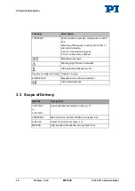
3.4 Suitable Controllers
The V-273 must be connected to a suitable controller. The following controllers from
PI are suitable for the operation of the V-273:
Controller
Description
C-413.20
PIMag® Motion Controller, 2 Channels, USB Interface,
OEM Board, Force Control Option
C-413.20A
PIMag® Motion Controller, 2 Channels, USB Interface,
Analog Inputs, OEM Board, Force Control Option
C-413.2G
PIMag® Motion Controller, 2 Channels, USB Interface,
Bench-Top Device, Force Control Option
C-413.2GA
PIMag® Motion Controller, 2 Channels, USB Interface,
Analog Inputs, Bench-Top Device, Force Control Option
PC software is included in the scope of delivery of the controllers from PI. The
operation of the controllers is described in the corresponding user manuals.
3.5 Technical Features
3.5.1 Linear Encoder
The V-273 is equipped with an optical linear encoder. For the resolution, refer to the
table in the "Specifications" section (p. 33).
Optical linear encoders measure the actual position directly (direct metrology).
Therefore, errors occurring in the drivetrain, such as nonlinearity, backlash or elastic
deformation, cannot influence the measurement of the position.
3.5.2 Reference Point Switch
The V-273 is equipped with a direction-sensing reference point switch, which is
located at about the midpoint of the travel range. This sensor transmits a TTL signal
that indicates whether the linear actuator is on the positive or negative side of the
reference point switch.
See the controller user manual and/or associated software manuals for the commands
which make use of the reference point signal.
For more information, see "Reference Point Switch Specifications" (p. 36).