


5 Installation
P-545 Nanopositioners
PZ272E
Version: 1.1.0
23
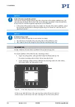
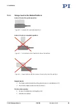
Mounting the P-545 onto an M-545 XY stage
1.
Align the P-545 on the M-545 so that the following conditions are met:
−
The mounting holes in the P-545's base body (p. 20) and in the M-545's motion
platform (depending on the model; see arrows in the figure) are in line.
−
The cable exit points in the desired direction.
2.
Insert the four M4 screws into the mounting holes in the base body of the P-545 (p. 20).
3.
Tighten the screws:
−
Pay attention to the specified torque range (p. 46) for the screws.
−
Make sure that the screw heads are fully countersunk.
5.4
Fixing the Load
NOTICE
Mechanical overload of the platform!
High torques during fastening of the load as well as heavy loads can overload the platform of
the P-545. Mechanical overload can cause damage to the piezo actuators, sensors, and flexures
of the P-545 and lead to loss of accuracy.
Avoid torques >0.5 Nm on the platform.
Do
not
exceed the maximum permissible loads according to the specifications (p. 37).
Hold the load and adhere to the specified torque range (p. 46) when tightening (or
loosening) the screws.
NOTICE
Warping of the P-545 when fixing loads with an uneven contact surface!
Fixing loads with an uneven contact surface could warp the P-545. Warping reduces the
accuracy.
Fix loads to the P-545 only when the surface contacting the P-545's platform has a flatness
of at least 100 μm.
For applications with large temperature fluctuations:
Mount loads onto the P-545 only if they have the same or similar thermal expansion
properties as the P-545 (e.g., loads made of aluminum).