L505M0004EN
‒
11/26/2018
User Manual
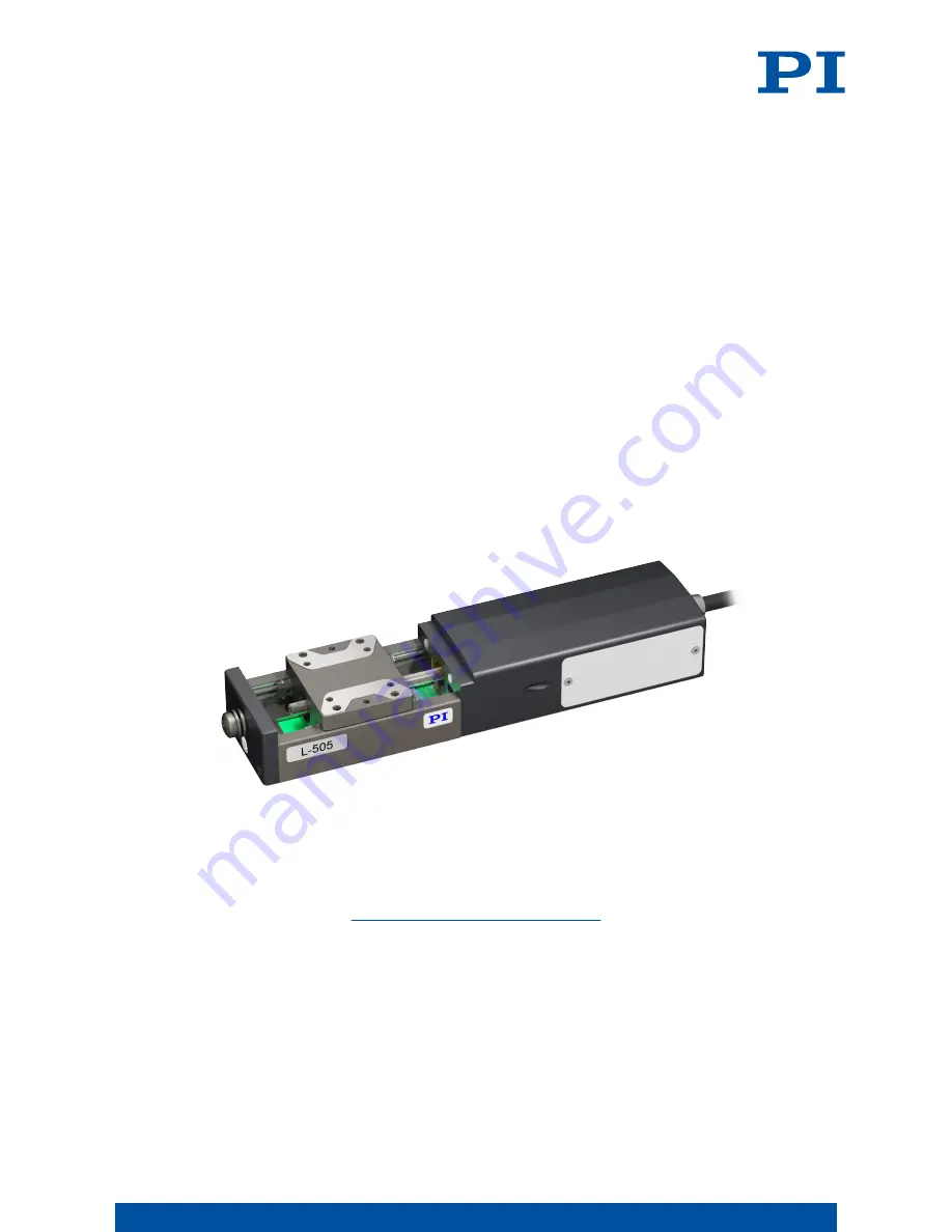
L-505.011200 LINEAR STAGE WITH STEPPER MOTOR
M O T I O N | P O S I T I O N I N G
Страница 1: ...L505M0004EN 11 26 2018 User Manual L 505 011200 LINEAR STAGE WITH STEPPER MOTOR M O T I O N P O S I T I O N I N G...
Страница 2: ...4 2 Scope of Delivery 9 4 3 Overview 10 4 3 1 Base Body 10 4 4 Suitable Electronics 10 4 5 Accessories 10 5 Unpacking 12 6 Installation 13 6 1 Mounting the L 505 011200 13 6 2 Connecting the L 505 011...
Страница 3: ...Conditions and Classifications 33 12 4 Dimensions 34 13 Old Equipment Disposal 35 14 Appendix 37 14 1 Pin Assignment 37 14 1 1 Drive Connector 37 14 2 Drive properties 38 14 3 Reference point switch...
Страница 4: ...With regard thereto Physik Instrumente PI GmbH Co KG reserves all rights The use of any text images and drawings is permitted only in part and only when indicating the source Original instructions Fir...
Страница 5: ...Controller The latest versions of the user manuals can be downloaded p 6 at www pi ws 2 3 Explanation of Symbols This chapter explains the symbols and markings used by PI in their user manuals 2 3 1...
Страница 6: ...l in illustrations can deviate from the actual circumstances Photographic illustrations may also differ and must not be seen as guaranteed properties 2 5 Downloading Manuals The latest versions of the...
Страница 7: ...a Click Search b Enter the product number up to the period e g L 505 into the search field c Click Start search or press the Enter key d If necessary Click Load more results at the bottom of the list...
Страница 8: ...0 may result in personal injury and or damage to the L 505 011200 Use the L 505 011200 only for its intended purpose and if it is in perfect condition Read the user manual Eliminate any faults and mal...
Страница 9: ...to order L505B1000 Mounting kit for mounting the L 505 011200 consisting of 4 socket head screws ISO 4762 M3 6 2 dowel pins ISO 8734 2m6 8 000036450 M4 screw set for protective earth consisting of 1 f...
Страница 10: ...to prevent the motion platform from colliding with the mechanical hard stop 4 4 Suitable Electronics The L 505 011200 must be connected to suitable electronics that supply the necessary voltage for op...
Страница 11: ...To order contact our customer service department p 30 4 PRODUCT DESCRIPTION L505M0004EN 11 26 2018 11 M O T I O N P O S I T I O N I N G...
Страница 12: ...ive caps 3 Compare the contents with the scope of delivery according to the contract and the delivery note 4 Inspect the contents for signs of damage If any parts are damaged or missing contact our cu...
Страница 13: ...to regulations CAUTION Risk of crushing by moving parts Risk of minor injuries from crushing between the moving parts of the L 505 011200 or the load and a fixed part or obstacle Use safeguards to pr...
Страница 14: ...that the corresponding mounting holes in the L 505 011200 and the surface overlap 3 Insert the screws into all accessible mounting holes and tighten 4 If necessary Repeat steps 1 to 3 for all conceale...
Страница 15: ...Nm 4 Make sure that the contact resistance is 0 1 at 25 A at all connection points relevant for attaching the protective earth conductor 6 3 Setting Up a Multi Axis System The L 505 011200 can be use...
Страница 16: ...NOTICE Protruding screw heads Protruding screw heads can damage the L 505 011200 Make sure that the screw heads are fully countersunk and cannot interfere with motion NOTICE Damage due to mechanical s...
Страница 17: ...l Accessories p 10 Designations in these instructions Horizontal positioner Forms the horizontal axis of the multi axis system Vertical positioner Forms the vertical axis of the multi axis system is a...
Страница 18: ...stems include the masses of the positioners to be moved when calculating the load NOTICE Unwanted changes in position with vertical mounting If the load exceeds the self locking of the L 505 011200 wh...
Страница 19: ...anical loading e g drag chain cables Tools and Accessories Mounting bracket see Optional Accessories p 10 mounting hardware in the scope of delivery of the L 505 4 screws ISO 4762 M3 6 A2 2 locating p...
Страница 20: ...ert two 2 mm m6 8 mm locating pins into the mounting bracket b Align the L 505 to the mounting bracket c Insert the M3 6 screws into the holes in the upper L 505 and tighten them 6 INSTALLATION L505M0...
Страница 21: ...6 5 Mounting the Load onto the L 505 011200 Overview 1 2 3 1 1 1 1 Screws 2 Load 6 INSTALLATION L505M0004EN 11 26 2018 21 M O T I O N P O S I T I O N I N G...
Страница 22: ...nd can damage the L 505 011200 Pay attention to the maximum permissible forces p 31 that may act on the motion platform In the case of multi axis systems include the masses of the positioners to be mo...
Страница 23: ...8 You have read and understood the user manual for the electronics used You have installed the electronics properly The electronics are switched off NOTICE Damage due to incorrect connection of the L...
Страница 24: ...high or incorrectly connected can cause damage to the L 505 011200 Pay attention to the operating voltage range p 33 which is specified for the L 505 011200 Pay attention to correct pin assignment p...
Страница 25: ...After every 2000 motion cycles Performing a Maintenance Run 1 Make sure that collisions between the L 505 011200 the load to be moved and the surroundings are not possible over the entire travel rang...
Страница 26: ...by Hand It can be necessary to move the motion platform manually to provide access to mounting holes for mounting screws in the base body of the positioner Requirements You have disconnected the L 505...
Страница 27: ...s Required Soft lint free cloth Mild cleaning agent or disinfectant If you have any questions on the auxiliary materials recommended for the L 505 011200 contact our customer service department p 30 N...
Страница 28: ...sive acceleration of the motion platform Determine the maximum velocity and accelera tion in the application that do not lead to step loss Reduced positioning accuracy When the L 505 011200 is mounted...
Страница 29: ...tion 1 Pay attention to the ambient conditions and classifications p 33 2 Pack the L 505 011200 in the original packaging 3 If the L 505 011200 is to be sent use a stable outer box 10 TRANSPORTATION L...
Страница 30: ...of the controller if applicable Version of the driver or the software if applicable Operating system on the PC if applicable If possible Take photographs or make videos of your system that can be sent...
Страница 31: ...2 5 Maximum velocity mm s max 10 Reference point switch Hall effect Reference point switch repeatability m typ 4 Limit switches Hall effect Linear crosstalk in Y with motion in X m typ 0 5 Linear cros...
Страница 32: ...Y N m max 6 Permissible torque in Z N m max 6 Overall mass kg 5 0 4 Moved mass unloaded g 0 07 Motor type Stepper motor Nominal voltage V 24 Nominal current RMS A max 0 6 Resistance 6 5 Inductance mH...
Страница 33: ...wer consump tion 48 V 4 W 12 3 Ambient Conditions and Classifications The following ambient conditions and classifications for the L 505 011200 must be observed Area of application For indoor use only...
Страница 34: ...e decimal places are separated by a comma in the drawings 0 0 Figure 3 Mounting holes in the L 505 011200 s motion platform Dimensions in mm Note that the decimal places are separated by a comma in th...
Страница 35: ...rder to fulfil the responsibility as the product manufacturer PI miCos undertakes environmentally correct disposal of all PI miCos equipment free of charge if it was made available to the market after...
Страница 36: ...oad is at the center of the motion platform Max push pull force Maximum force in the direction of motion The L 505 011200 could exert higher forces however will shorten the lifetime In the case of ver...
Страница 37: ...t Motor voltage phase B 8 Not connected 9 Not connected 10 Output Reference point switch 11 Output Limit switch negative 12 Output Limit switch positive 13 Not connected 14 Not connected 15 Not connec...
Страница 38: ...ensor Supply voltage 5 V Signal output Open collector Signal logic Direction sensing via different signal levels on the left and right of the reference point switch 0 1 Ref Positive direction of motio...
Страница 39: ...Figure 5 L 505 at the negative limit switch Figure 6 L 505 at the positive limit switch 14 APPENDIX L505M0004EN 11 26 2018 39 M O T I O N P O S I T I O N I N G...
Страница 40: ...1200 in accordance with the following European directives EMC Directive RoHS Directive The applied standards certifying the conformity are listed below EMC EN 61326 1 Safety EN 61010 1 RoHS EN 50581 1...