3. Attach one of these to the 5VDC terminal on the DAQC2plate digital output terminal block.
4. Connect the other red wire to the Flyback Protection terminal. Route a black wire to DOUT0 of the
terminal block.
5. Assuming the DAQC2plate board is at address 0, type DAQC2.setDOUTbit(0,0) to turn the solenoid on.
6. Type DAQC2.clrDOUTbit(0,0) to turn off the solenoid.
Analog Inputs (ADC)
Use the analog input to measure sensors that produce a variable output voltage. These eight terminals can be
used for measuring voltage, temperature, humidity, light brightness, potentiometers, strain gauges, and much
more.
Connector
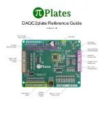
Refer to the diagram at the top of this page as well as the one below to locate the Analog Input terminals:
Specifications
● Eight inputs
● 16 bit resolution (16 bits is obtained by averaging 128 fourteen bit values)
● ~366μV per bit
● Maximum input voltage range: ±12 volts
● >0.1% precision
● SNR of 75dB with a 10VDC input voltage
● All inputs have ESD protection
● All inputs have over and undervoltage protection
● Bandwidth of each input is limited to 50Khz to minimize high frequency noise.
● All inputs are factory calibrated
● Note that a floating input will read 1.333 volts.
● Dedicated input (channel 8) for measuring power supply voltage (accurate to ±1.5%)
Functions
addr
must be in the range of 0 through 7
channel
must be in the range of 0 through 8
● getADC(addr, channel) - return voltage from single channel. Reading channel 8 will return the 5VDC
power supply voltage.
Содержание DAQC2plate
Страница 1: ...DAQC2plate Reference Guide Version 1 04 ...


