


Development Kit CANopen Chip164
6
© SYS TEC electronic GmbH 2003
L-1006e_2
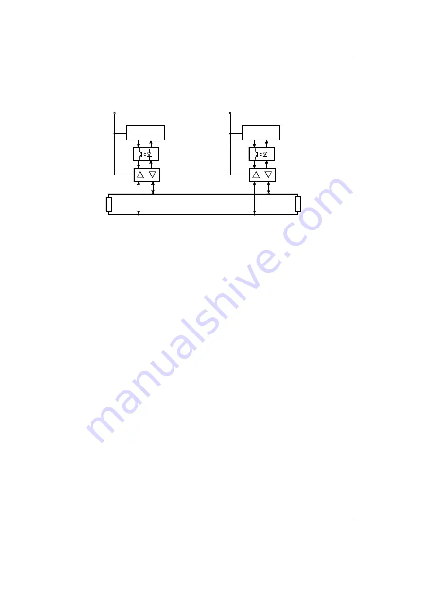
shows the general CAN bus connection circuitry. The
galvanic isolation is not included in the Development Kit.
Figure 6:
CAN Bus Connection Circuitry
2.4
Installing the PCAN-Dongle
Connecting the PCAN-Dongle to your host-PC should only be done
when the computer or laptop is powered off.
•
First connect the PCAN-Dongle, using its DB-25 plug, to the
parallel printer port of a host-PC (desktop or laptop).
•
Power for the PCAN-Dongle is supplied via the keyboard
connector.
•
Insert either the PS/2 or DIN plug into the keyboard socket on the
host PC.
•
Connect your keyboard cable to the PCAN-Dongle power supply
socket.
•
Turn on your host-PC.
•
The red LED on the PCAN-Dongle lights if power is supplied to
the device.
MC
(C50 5C)
VCC
5V DC
galvani
i
che
so l at iung
VCC
5V DC
Transceiver
120 Ohm
120 Ohm
CAN_High
CAN_Low
MC
(C50 5C)
Pin 2
Pin 2
Pin 2
Pin 7
Pin 7
galvanic
Isolation


