background image

Owner’s Manual 

ENGLISH


47


Reclining Gas Spring Backrest


The reclining gas spring backrest is pre-assembled in our factory. When replacing a 
standard backrest with a reclining gas spring backrest, you must follow the steps in the 
order indicated. 

Note 

- The reclining gas spring mechanism cannot be installed with dynamic back 

posts. 

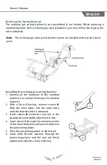
Installing the reclining gas spring backrest 

1. Remove all the  hardware of the standard

backrest (see section 

Removing the standard

backrest

).

2. With a 5mm Allen key, remove screws 

A

.

Slide the inner tubes into the outer tube,
until the desired width is obtained.

3. Insert sleeves 

B

  inside the seat rail, in the

appropriate seat depth adjustment holes.

4. Insert sleeve 

C

 through the mounting holes

of the lower back post and place in between
the positioning plates.

5. Place the positioning plates as illustrated.
6. Insert bolts 

D

  with washers through the

positioning plates and the seat rail, firmly
tighten bolts 

D

 with a 5mm Allen key. 

R

e

vision 0 

July 

202

2


Содержание NeoX

Страница 1: ...Owner s Manual This booklet contains important information about this product Please give to the owner upon delivery...

Страница 2: ...llow you to use our product in a safe and optimal way For all adjustments and settings we strongly recommend you contact your distributor Physipro Inc relieves itself of all liability should physical...

Страница 3: ...air occupant 19 Warnings Falls and Tips 20 Changing clothes 20 Grabbing an item bending over or leaning 20 Transfers 21 Obstacles 21 Going up a sidewalk or step 22 Going down a sidewalk or step 22 Goi...

Страница 4: ...obstacles with the rear caster tilt mechanism 36 Front Casters 38 Assembling and installing the front caster fork 38 Installing caster wheels 39 Seat 40 Modifying seat depth 40 Modifying seat width o...

Страница 5: ...ng legrest length 61 Removing legrest 61 Adjusting legrest angle 61 Wheel Locks 62 Installing wheel locks 62 Adjusting the brake force 62 Using wheel locks 63 Attendant Wheel Lock 4 wheel or 6 wheel o...

Страница 6: ...NEOXTM Dynamic wheelchair ENGLISH 6 Maintenance 80 Maintenance Checklist 80 Replacement Parts 83 Repair Services 83 7 Storage and Shipping 84 Storage 84 Shipping 84 8 Warranty 85...

Страница 7: ...d at the very front of the frame this ensures that knee height remains constant regardless of the wheelchair s tilt angle This feature facilitates lower limb propulsion The NeoxTM Dynamic wheelchair o...

Страница 8: ...with angle and height adjustments D Push handles with grip covers with height and orientation adjustments E Armrest desk length flip back or removable F Armrest foam pad desk length flat G Legrest br...

Страница 9: ...er form NEOXTMDYNAMIC Substitutional Components Sling backrest with tension adjustment Stroller bar with grip cover with height and orientation adjustment Armrest full length flip back or removable Ar...

Страница 10: ...double Heel support strap adjustable Wheel lock handle extension telescopic or fixed Spoke guard Reflective safety stickers Backrest tension bar Headrest support mounting fixture for backrest tension...

Страница 11: ...85 to 120 Dynamic Backrest 85 to 110 Adjustable in increments of 5 Reclining Gas Spring Backrest 85 to 130 continuous adjustment Backrest height Method of measurement Part 7 ISO 7176 7 section 7 3 8...

Страница 12: ...hod of measurement ISO 7176 5 section 8 12 N A Pivot width Method of measurement ISO 7176 5 section 8 11 51 1295 mm Push handle height 38 965 mm Required width of angled corridor 42 1080 mm Required d...

Страница 13: ...C STABILITY Tipping angle of wheelchair in the least stable configuration left side Method of measurement ISO 7176 1 section 10 2 22 9 Tipping angle of wheelchair in the least stable configuration rig...

Страница 14: ...o the test requirements of CAL 117 WHEELCHAIR FOR USE AS A SEAT IN A MOTOR VEHICLE Declaration that this wheelchair model conforms with the requirements of ISO 7176 19 and is designed to be used in a...

Страница 15: ...urement points are removed they cannot be replaced and your wheelchair will no longer comply with ISO DIS 7176 19 19 For more information please consult the Transport section of this manual Note that...

Страница 16: ...e sure all parts operate without abnormal noises vibrations or irregular movements The presence of one of these conditions may indicate that the propulsion wheels are deflated that a part is not adequ...

Страница 17: ...ting to lift oneself Never use detachable or removable parts to lift wheelchair Always use the rigid parts of the frame when lifting the wheelchair Be careful not to pinch your fingers when installing...

Страница 18: ...maximum load capacity of your wheelchair is indicated in the Technical Specifications section Never transport more than one person in a wheelchair The wheelchair was designed for one person only Surr...

Страница 19: ...s also advised When moving on a public road be extremely careful and pay close attention to the dangers and obstacles on the road such as potholes and uneven or cracked surfaces Never engage on roads...

Страница 20: ...and as near as possible to the desired item with the front caster wheels pointed forward To correctly position the wheelchair move your wheelchair forward slightly beyond the item you want to obtain...

Страница 21: ...w moments to familiarize yourself with your surroundings and locate any potential obstacles that may hinder your movements This will allow you to determine the best way to move forward safely and avoi...

Страница 22: ...ine the wheelchair backwards to lift the front caster wheels from the ground and place them onto the platform 5 The attendant must push the wheelchair forward until the propulsion wheels are in contac...

Страница 23: ...help of two attendants is required and the following procedure should be followed 1 Place the back of the wheelchair towards the stairs The first attendant must stand behind the wheelchair and firmly...

Страница 24: ...be affected A change in posture and or weight distribution will modify the center of balance Fixing objects to the backrest will also affect the center of balance Moving backwards Caution is in order...

Страница 25: ...ection on a slope or a ramp An inclined surface will impact the wheelchair s center of balance and increases the risk of tipping over You must always adjust your body position to keep a steady balance...

Страница 26: ...essure to the handrims by letting them slowly slip through your hands 3 Always control the direction of your wheelchair and move in a straight line when descending slope Going up a slope or a ramp 1 B...

Страница 27: ...et 3 4 1 Imperial Allen keys 7 64 1 4 7 16 Two 3 4 socket wrenches 19 mm reversible ratchet Phillips screwdriver WARNING Neveruse pneumatic or electric tools these may damage your wheelchair WARNING A...

Страница 28: ...Position Caster Wheel Position Seat to Floor Height Frame plate adjustments 12 305 mm 5 130 mm P3 D 13 to 17 330 to 430 mm 6 150 mm P3 C 14 to 18 360 to 460 mm 8 200 mm P4 D 15 to 19 380 to 480 mm 20...

Страница 29: ...plied and pre assembled to dynamic forks with a diameter of 5 127 mm or 6 152 mm Modifying the position of the axle mounting block 1 Remove propulsion wheels by referring to section Removing propulsio...

Страница 30: ...ough space in front of the propulsion wheels to properly install wheel locks Modifying the position of the caster wheels 1 With two 13 mm wrenches unfasten bolt A and remove spacers if necessary 2 Ref...

Страница 31: ...ench secure the axle bushing E in place with lock washers D and nut C 4 Insert axle A through wheel hub B and axle bushing E 5 Tighten nut G with a socket wrench while holding axle A in place with ano...

Страница 32: ...ert axle A through wheel hub B and axle bushing E Removing propulsion wheels Quick Release axle 1 Unfasten nut C and remove lock washers D 2 Slide axle A out of wheel hub B and axle bushing E Adjustin...

Страница 33: ...ays make sure the retaining balls of the quick release axle project completely out from the axle bushing and that the tip of the ball lock pin is perfectly aligned with the tip of the axle before usin...

Страница 34: ...lity and ensure there is enough space in front of the propulsion wheels to properly install wheel locks Propulsion wheel lateral positioning This modification is used to move the propulsion wheels clo...

Страница 35: ...for the recommended pressure 2 Connect pump to inner tube valve 3 Inflate tire using a pressure gauge to regularly check tire pressure Do not exceed the recommended tire pressure Note Tire pressure c...

Страница 36: ...d eyelet C 2 Fold the strap over and reinsert through clamping ring B 3 Adjust strap tension 4 Once the desired strap tension is reached tighten screw D with a 3mm Allen Key Clearing obstacles with th...

Страница 37: ...ls should no longer touch the ground 4 Once the rear caster tilt mechanism is activated the front caster wheels will lift upwards Keep foot pressed down on strap and move the wheelchair forward to sur...

Страница 38: ...width of 1 32 mm Assembling and installing the front caster fork 1 Install spacer A on bolt B 2 Insert bolt B with spacer A through fork C 3 Install spacers D and nut E onto bolt B 4 Remove cap on ca...

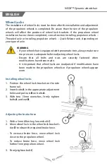
Страница 39: ...ir must be performed by a qualified technician Failure to observe this warning may lead to serious injury to the occupant or any other individual who is near the wheelchair If your wheelchair is equip...

Страница 40: ...multaneously adjust footrest depth 6 Insert screws C in the appropriate adjustment holes and tighten screws firmly 7 With a 4mm Allen key and a 10mm wrench unfasten bolt assembly F at the rear section...

Страница 41: ...central screws of the backrest tension bar see section Installing the tension bar 6 If a stroller bar is installed unfasten both central screws with a 4mm Allen key see section Installing the stroller...

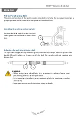
Страница 42: ...ghten screw B with a 4mm Allen key Adjusting the pelvic positioning belt To adjust the length of the positioning belt slide the belt strap C into the plastic slide buckle D and tighten or loosen until...

Страница 43: ...lining gas spring Backrest 16 to 20 406 to 508 mm 18 to 22 457 to 559 mm 16 to 20 406 to 508 mm 21 to 25 533 to 635 mm 23 to 27 584 to 686 mm 21 to 25 533 to 635 mm Modifying back post height The foll...

Страница 44: ...t only Removing the standard backrest The Standard backrest can be removed and replaced by a Dynamic or Reclining gas spring backrest if needed The following steps explain how to remove the standard b...

Страница 45: ...krest angle you must decrease the tension of the dynamic backrest by turning the handle counterclockwise 4 With two 10mm wrenches fasten bolts B with washers C and nuts D 5 Reinstall and adjust the he...

Страница 46: ...3 Once the bolts are removed reposition the back post at the desired angle 4 Reinsert bolts F in the adjustment holes corresponding to the desired angle and tighten firmly 5 Readjust the backrest tens...

Страница 47: ...he hardware of the standard backrest see section Removing the standard backrest 2 With a 5mm Allen key remove screws A Slide the inner tubes into the outer tube until the desired width is obtained 3 I...

Страница 48: ...n screws H with a 4mm Allen key 11 Insert the upper back post into the lower back post and adjust the height 12 Reinstall backrest tension bar and stroller bar if applicable 13 Install the reclining b...

Страница 49: ...bes 4 With a 4mm Allen key firmly tighten screws D 5 With a 3mm Allen key firmly tighten screws A To remove tension bar completely unfasten and remove screws D Installing a headrest support mounting f...

Страница 50: ...ck posts you can procced directly to steps 6 to 9 1 With a 4mm Allen key unfasten screws B and remove tension bar A 2 With a Philips screwdriver remove activation lever s see section Installing an act...

Страница 51: ...lly lock into place WARNING Never lift or pull your wheelchair with the stroller bar The stroller bar was designed to push and steer the wheelchair only Improper use may damage or break the stroller b...

Страница 52: ...12 30 10 30 8 14 30 16 30 14 30 10 15 30 20 30 17 30 13 16 30 24 30 21 30 16 17 30 28 30 24 30 19 20 13 30 5 30 6 30 3 14 30 9 30 9 30 7 15 30 13 30 12 30 8 16 30 16 30 16 30 11 17 30 21 30 19 30 14...

Страница 53: ...t angle to improve safety during cylinder replacement 2 Unfasten and remove the cylinder cable 3 With a 4mm wrench unfasten and remove screws A 4 With a 4mm Allen key and a 10mm wrench unfasten should...

Страница 54: ...Activate tilt mechanism by pressing and holding both activation levers B simultaneously 3 Once the desired tilt angle is obtained release both activation levers B 4 If needed the maximum tilt angle ca...

Страница 55: ...power tilt mechanism 1 To tilt your wheelchair backwards press the controller lever upwards Note Once maximum tilt is obtained the tilting mechanism will stop even if the controller lever is still pr...

Страница 56: ...is a risk of explosion e g Garage The charger must be kept out of the reach of children Charge battery in a well ventilated area Unplug the battery charger from power outlet when the battery charger...

Страница 57: ...e positioning plate 3 Reinsert screw A through the receiver positioning plates and seat rail 4 Place nut B on screw A and firmly tighten using a 4mm Allen key and a 10mm wrench to hold nut B in place...

Страница 58: ...hold nut C in place Installing the T type armrest 1 Press and hold down lever D 2 Insert armrest into receiver A 3 Release lever D to lock armrest in place Adjusting the T type armrest height 1 Press...

Страница 59: ...508 mm Footrest 90 10 to 20 254 mm to 508 mm Adjustable in increments of Installing the footrest 1 Insert pivot saddle A into the receiver on the front frame tube 2 Turn the footrest inwards until the...

Страница 60: ...the footplate 1 With a 4mm Allen key loosen both screws D without removing them 2 Pivot the footplate until the desired horizontal angle is obtained 3 Firmly tighten both screws D Adjusting the vertic...

Страница 61: ...the appropriate adjustment holes 4 Tighten all 4 bolts B firmly Adjusting legrest length 1 With a 4mm Allen key unfasten screws C 2 Raise or lower the inner adjustment tube until the desired length i...

Страница 62: ...justing wheel locks Ensure that all bolts and nuts are securely fastened when modifications have been made It is important that wheel locks are readjusted if modifications have been made to the propul...

Страница 63: ...ar should embed to into the tire Using wheel locks Push to lock To lock wheels push handle E forward To unlock wheels pull handle E backwards Pull to lock To lock wheels pull handle E backwards To unl...

Страница 64: ...ing the brake force 1 With two 13mm wrenches remove bolts F 2 Move the attendant wheel lock brackets forward or backwards to obtain the required brake force To increase brake force move attendant whee...

Страница 65: ...econd anti tip Adjusting anti tips Once anti tips are installed it is important to adjust their height 1 Press button pin B and raise or lower the anti tip s adjustment tube until button pin B is posi...

Страница 66: ...sure anti tips are locked in place and that the button pins and lock pin protrude from the receiver mounting holes Anti tips may be less efficient on wet surfaces on clay or sandy soils in snow or gra...

Страница 67: ...en stop the occupant may be ejected from the wheelchair and may sustain serious injuries The wheelchair s belts and harnesses are not designed to secure the occupant in these circumstances and may inc...

Страница 68: ...at in a motor vehicle Note Compliance with this standard does prohibit using the wheelchair in a rear facing position in larger adapted vehicles that are equipped with rear facing wheelchair passenger...

Страница 69: ...Physipro Inc cannot guarantee the performance of these wheelchairs Compliance with the ISO DIS 7176 19 2019 standard does not prevent injury or death of the wheelchair occupant if implicated in a vehi...

Страница 70: ...t and shoulder belt must be used to reduce the risk of head or chest injuries that may be sustained by impact with components of the vehicle Please note that the size of the wheelchair may reduce mano...

Страница 71: ...n A regular visual inspection of the complete restraint system for adapted transport is required Install tie down straps to the wheelchair s identified securement point locations see Figure 1 Secureme...

Страница 72: ...traps to the front securement points make se the vehicle s front anchor points are spaced slightly wider than the wheelchair this ensures better lateral stability see Figure 3 Figure 3 WARNING The Neo...

Страница 73: ...hes 66 cm minimum Note The front clear zone may not be achievable for wheelchair seated drivers Rear clear zone RCZ The rear clear zone is measured from the rearmost point of the occupant s head and m...

Страница 74: ...cannot be removed such as with respirators and IV supports the equipment must be placed as far away as possible from the occupant and wrapped in a shock absorbing material Make sure the protective pac...

Страница 75: ...the horizontal If these requirements cannot be reached the pelvic belt can be positioned securely in the optional zone at an angle between 30 and 45 degrees to the horizontal see Figure 6 Figure 6 2...

Страница 76: ...Figure 7 4 The pelvic and shoulder belts should fit snugly against the occupant s body and should never be held away from the body by any of the wheelchair s components or parts such as the armrest or...

Страница 77: ...components cannot interfere with the buckle and activate the opening mechanism in the event of a collision Wheelchair rating in accordance with the ISO DIS 7176 19 2019 standard Rating for ease of us...

Страница 78: ...is recommended 1 Clean painted surfaces with a mild soap or a neutral based detergent and water 2 ounces 6 cl for 8L of water and rinse thoroughly 2 Dry with a clean cloth to absorb excess moisture T...

Страница 79: ...rfaces with a clean cloth 3 Allow to air dry completely Disinfection Disinfection helps destroy infectious agents and eliminate pathogenic micro organisms with the use of bactericidal or virucidal cle...

Страница 80: ...d twice a year to ensure your wheelchair s proper operation Maintenance Checklist Weekly Monthly Every 6 months General Clean all wheelchair parts Make sure wheelchair rolls in a straight line Make su...

Страница 81: ...ot leaking oil Check condition of cables and make sure they are well attached Power Tilt System if applicable Make sure activation levers and electric cylinders are functioning properly Check conditio...

Страница 82: ...e sure the Dynamic backrest functions properly if applicable Make sure the Reclining Gas Spring backrest functions properly if applicable Check the condition of seat and backrest covers Pelvic positio...

Страница 83: ...deviation misaligned wheels loose bolts misaligned caster forks broken or loose spokes broken bearings or if replacement parts are needed please contact our customer service at 1 800 823 2252 or at o...

Страница 84: ...required To avoid damaging your wheelchair never store your wheelchair in an excessively humid area or leave your wheelchair outside for long periods of time in bad weather such as rain snow or extre...

Страница 85: ...st defects in materials and workmanship 2 years Parts and labor for original defects in material and workmanship of the wheelchair components and optional components New parts that have been replaced...

Страница 86: ...ovided in the user manual Damage that occurs to the product during transportation Replacement and repairs carried out during the warranty period must be made with the original parts and components To...

Страница 87: ...Owner s Manual ENGLISH 85 Notes Revision 0 July 2022...

Страница 88: ...SIPRO INC 370 10e Avenue Sud Sherbrooke Qu bec J1G 2R7 Canada T 1 800 668 2252 F 819 565 3337 info physipro com order physipro com Europe Importateur SASU PHYSIPRO IMPORT T 02 41 69 38 01 F 02 41 69 4...

Отзывы: