background image


12 Glossary 

H-850 Hexapod Microrobot 

MS202E 

Version: 2.3.0 

69 

User-defined coordinate system 

Using the controller, custom coordinate systems can be defined and used instead of the default 

coordinate systems. 
Work with user-defined coordinate systems and the work-and-tool concept is described in the 

C887T0007 technical note. 


Workspace 

The entirety of all combinations of translations and rotations that the hexapod can approach 

from the current position is referred to as the workspace. 
The workspace can be limited by the following external factors: 


Installation space 


Dimensions and position of the load 


Center of rotation 

The center of rotation describes the intersection of the rotational axes U, V, and W. When the 

default settings for the coordinate system and the center of rotation are used, the center of 

rotation after a reference move is located at the origin of the coordinate system (0,0,0), see the 

dimensional drawing of the hexapod (p. 61). 
The center of rotation always moves together with the platform. 
Depending on the active --> operating coordinate system, the center of rotation can be moved 

from the origin of the coordinate system in the X and/or Y and/or Z direction with the 

SPI


command. The center of rotation that can be moved using the 

SPI

 command is also referred 

to as "pivot point". 


Hexapod system 

The combination of hexapod, controller, cable set, and power supply is referred to as "hexapod 

system" in this manual. 


Default coordinate system 

The X, Y, and Z axes of the Cartesian coordinate system are always spatially fixed, i.e., the 

coordinate system does not move when the platform of the hexapod moves. The X, Y and Z 

axes are also referred to as translational axes. 
The intersection of the axes X, Y, and Z of the spatially fixed Cartesian coordinate system (0,0,0) 

is referred to as the origin. 

12


Glossary 

Содержание H-850 Series

Страница 1: ...ny Phone 49 721 4846 0 Fax 49 721 4846 1019 Email info pi ws www pi ws MS202E H 850 Hexapod Microrobot User Manual Version 2 3 0 Date 03 12 2019 This document describes the following hexapod microrobots H 850 H2 H 850 H2A H 850 H2I H 850 H2V H 850 G2 H 850 G2A H 850 G2I H 850 G2V ...

Страница 2: ...rademark of iC Haus GmbH 2019 Physik Instrumente PI GmbH Co KG Karlsruhe Germany The text photographs and drawings in this manual are protected by copyright With regard thereto Physik Instrumente PI GmbH Co KG retains all the rights The use of any text images and drawings is permitted only in part and only when indicating the source Original instructions First printing 03 12 2019 Document number M...

Страница 3: ...le Controllers 8 3 4 Product View 9 3 5 Scope of Delivery 9 3 6 Accessories 10 3 7 Technical Features 12 3 7 1 Struts 12 3 7 2 Reference Switch and Limit Switches 13 3 7 3 Control 13 3 7 4 Motion 13 3 7 5 ID Chip 17 4 Unpacking 19 4 1 Unpacking the Hexapod 19 4 2 Removing the Transport Safeguard 20 4 2 1 Removing the Transport Safeguard for the H 850 x2 and x2V Models 20 4 2 2 Removing the Transpo...

Страница 4: ... Transport Safeguard 42 7 2 2 Packing the Hexapod 46 7 3 Cleaning the Hexapod 49 8 Troubleshooting 51 9 Customer Service 53 10 Technical Data 55 10 1 Specifications 55 10 1 1 Data Table 55 10 1 2 Specifications for Vacuum Compatible Versions 58 10 1 3 Maximum Ratings 60 10 2 Cable Set Specifications 60 10 3 Ambient Conditions and Classifications 61 10 4 Dimensions 61 10 5 Pin Assignment 63 10 5 1 ...

Страница 5: ...ing of basic servo systems as well as motion control concepts and applicable safety procedures The latest versions of the user manuals are available for download p 3 on our website 1 2 Symbols and Typographic Conventions The following symbols and typographic conventions are used in this user manual CAUTION Dangerous situation Failure to comply could lead to minor injury Precautionary measures for ...

Страница 6: ...umstances Photographic illustrations may also differ and must not be seen as guaranteed properties 1 4 Other Applicable Documents The devices and software tools from PI mentioned in this documentation are described in their own manuals Device program Document no Document content C 887 5xx controller MS247EK Short instructions for hexapod systems MS244E User manual C887T0011 EtherCAT interface of t...

Страница 7: ...tment p 53 Downloading manuals 1 Open the website www pi ws 2 Search the website for the product number e g P 882 or the product family e g PICMA bender 3 Click the corresponding product to open the product detail page 4 Click Downloads The manuals are shown under Documentation 5 Click the desired manual and fill out the inquiry form The download link will then be sent to the email address entered...

Страница 8: ......

Страница 9: ...s intended in conjunction with a suitable controller available from PI p 8 which coordinates all motion of the hexapod 2 2 General Safety Instructions The H 850 is built according to state of the art technology and recognized safety standards Improper use can result in personal injury and or damage to the H 850 Use the H 850 for its intended purpose only and only when it is in perfect technical co...

Страница 10: ...H 850 only after you have read and understood this user manual Personnel qualification The H 850 may only be installed started operated maintained and cleaned by authorized and appropriately qualified personnel 2 4 Measures for Handling Vacuum Compatible Products When handling the vacuum version of the hexapod attention must be paid to appropriate cleanliness At PI all parts are cleaned before ass...

Страница 11: ...es The center of rotation moves together with the motion platform High accuracy and step resolution in all axes No accumulation of errors of individual axes No friction and torques from moving cables The hexapod is controlled with a controller that can be ordered separately from PI p 8 The position commands to the controller are entered as Cartesian coordinates 3 2 Model Overview Model Designation...

Страница 12: ...able Controllers Model Description C 887 52 6 axis controller for hexapods TCP IP RS 232 benchtop device incl control of two additional axes C 887 521 6 axis controller for hexapods TCP IP RS 232 benchtop device incl control of two additional axes analog inputs C 887 522 6 axis controller for hexapods TCP IP RS 232 benchtop device incl control of two additional axes motion stop C 887 523 6 axis co...

Страница 13: ...cope of Delivery Order number Components H 850 Hexapod according to your order p 7 000015165 Snap on ferrite Cable set for all H 850 models K040B0478 or K040B0241 Data transmission cable HD D sub 78 f m 1 1 3 m The K040B0478 drag chain compatible cable is supplied with the H 850 G2A G2I H2A and H2I models The K040B0241 cable is supplied with the H 850 G2 H2 H2V and G2V models and is not drag chain...

Страница 14: ...al note on unpacking the hexapod MS247EK Short instructions for hexapod systems Screw sets and tools 000034605 Mounting kit 6 socket head screws M6 30 ISO 4762 1 hex key 5 0 DIN 911 000077312 Double open end wrench 10 x 13 mm DIN 895 000036450 Accessories for connecting to the grounding system 1 flat head screw with cross recess M4x8 ISO 7045 2 flat washers form A 4 3 DIN 7090 2 safety washers Sch...

Страница 15: ...sisting of Designation Length Item number Data transmission cable HD D sub 78 f m 1 1 7 5 m K040B0295 Power supply cable M12 m f 1 1 7 5 m K060B0223 C 887 5A10 Hexapod cable set 10 m consisting of Designation Length Item number Data transmission cable HD D sub 78 f m 1 1 10 m K040B0245 Power supply cable M12 m f 1 1 10 m K060B0224 C 887 5B10 Hexapod cable set 10 m drag chain compatible consisting ...

Страница 16: ...r adapter 000012097 See Cable Set Specifications p 60 for more information The length refers to the cable between the power adapter and the hexapod To order contact our customer service department p 53 3 7 Technical Features 3 7 1 Struts The hexapod has six adjustable length struts Each strut carries out linear motion Each set of settings of the six struts defines a position of the motion platform...

Страница 17: ...axes The velocities and accelerations of the struts are calculated so that all struts start and stop at the same time Every time the controller of a hexapod equipped with incremental encoders is switched on or rebooted the hexapod must complete a reference move in which each strut moves to its reference switch After the reference move the motion platform is in the reference position and can be com...

Страница 18: ... at the origin of the coordinate system 0 0 0 For further information see the glossary p 69 Rotation Rotations take place around the rotational axes U V and W The rotational axes meet at the center of rotation also referred to as pivot point The rotational axes and therefore also the center of rotation always move together with the platform of the hexapod see also the example below for consecutive...

Страница 19: ...Round platform replaced by T shaped platform Coordinate system shown shifted Center of rotation in the top left corner of the platform 1 The U axis is commanded to move to position 10 The rotation around the U axis tilts the rotational axes V and W Figure 3 Rotation around the U axis Platform in reference position Platform position U 10 U parallel to spatially fixed X axis ...

Страница 20: ...o position 10 The rotation takes place around rotational axis V which was tilted during the previous rotation The rotation around the V axis tilts the rotational axes U and W Figure 4 Rotation around the V axis Platform in reference position Platform position U 10 V 10 U and V parallel to the platform level ...

Страница 21: ...5 3 7 5 ID Chip The hexapod has an ID chip that contains data on the type of hexapod its serial number and the date of manufacture The data is loaded from the ID chip when the controller is switched on or rebooted Depending on the data loaded the controller keeps the current configuration or installs a new configuration For simple replacement the configuration data for all standard hexapods is sto...

Страница 22: ......

Страница 23: ...rapped twice in vacuum compatible film Touch the hexapod only with powder free gloves If necessary wipe the hexapod clean after unpacking 4 1 Unpacking the Hexapod Store the packaging and the transport safeguard Keep all packaging material and the transport safeguard in case the product needs to be transported later Unpacking the hexapod 1 Open the outer box 2 Remove the foam cover 3 Open the inne...

Страница 24: ...he screw set p 9 supplied Removing the transport safeguard for the H 850 x2 and x2V models 1 Use the hex key to loosen the 4 screws M6x20 used for securing the transport safeguard to the sides of the base plate 2 Use the hex key to unscrew the 2 screws M6x30 used for securing the transport safeguard to the motion platform The screw heads are located on the bottom of the motion platform 3 Remove th...

Страница 25: ...x2I models 1 Loosen the 4 nuts M8 used for securing the transport safeguard s cover to the struts 2 Remove the nuts and the corresponding flat washers 3 Loosen the 4 screws M6x16 used for holding the transport safeguard s cover on the motion platform 4 Remove the screws and the corresponding flat washers 5 Remove the transport safeguard s cover 6 Unscrew the 4 struts of the transport safeguard fro...

Страница 26: ......

Страница 27: ...the load of the hexapod with a simulation program p 24 The limit values determined with the simulation program are only valid when the controller has the servo mode switched on for the axes of the motion platform of the connected hexapod Before installing the load determine the workspace of the hexapod with a simulation program p 24 The limits of the workspace vary according to the current positio...

Страница 28: ...e the A000T0068 technical note Determining the workspace and the permissible load of the hexapod Follow the instructions in the A000T0068 technical note to determine the workspace and the limit value for the load of the hexapod with the simulation program The limit values in the following table serve as a guide They only apply when the center of mass is at the origin of the default coordinate syst...

Страница 29: ...e is included in the scope of delivery of the cable set The snap on ferrite is intended for permanent attachment to the hexapod side cable of the power supply When attaching the snap on ferrite make sure that it is correctly positioned on the cable The snap on ferrite can only be removed with special tools not included in the scope of delivery 000015165 snap on ferrite Attach the snap on ferrite t...

Страница 30: ...es of the snap on ferrite around the cable until the lock engages 5 4 Grounding the Hexapod The hexapod is not grounded via the power supply cable If a functional grounding is required for potential equalization 1 Connect the base plate to the grounding system For connection use the supplied accessories p 9 and the M4 hole with an 8 mm depth marked with the ground connection symbol p 61 2 Connect ...

Страница 31: ...7 not in the scope of delivery Mounting the hexapod 1 Make the necessary holes in the surface Six M6 threaded holes for mounting with M6x30 screws Optional Two locating holes with Ø 8 mm H7 for accommodating locating pins The arrangement of the six mounting holes as well as the two locating holes in the base plate of the hexapod can be found in the dimensional drawing p 61 2 If you use locating pi...

Страница 32: ...e motion platform or the depth of the mounting holes p 61 together with the load to be mounted Only use screws that do not project under the motion platform after being screwed in Only mount the hexapod and the load on the mounting fixtures holes intended for this purpose Requirements You have read and understood the general notes on installation p 23 You have determined the permissible load and t...

Страница 33: ...t the locating pins are inserted into the corresponding locating holes on the other side The layout of the mounting and locating holes in the motion platform of the hexapod as well as the tolerance values can be found in the dimensional drawing p 61 2 Use the screws to fix the load to the selected mounting holes in the motion platform 5 7 Optional Removing the Coordinate Cube You can remove the co...

Страница 34: ...dings When connecting the line driver boxes observe the channel assignment that is specified on the labeling of the sockets and connectors INFORMATION When a cable set with line driver boxes is used The 24 V Out 7 A connection on the controller is not available for the hexapod because this connection is required for the power supply of the hexapod side line driver box A C 887 5PS power supply for ...

Страница 35: ...cessary Installing vacuum feedthroughs Figure 10 Vacuum feedthrough for data transmission 4668 dimensions in mm B 4 holes Ø6 x 45 for M3 countersunk screw Install the vacuum feedthrough for data transmission 4668 so that the HD Sub D 78 socket f is in the vacuum chamber ...

Страница 36: ...nnection is in the vacuum chamber Connecting the hexapod to the controller Connect the hexapod and the controller to each other Observe the connection diagram that matches your cable set see below Observe the assignment that is given by the labeling on the sockets connectors and cables Observe the mechanical coding of connectors and sockets Do not use force Use the integrated screws to secure the ...

Страница 37: ...ut line driver boxes Panel plug connector male Socket connector female Controller Refer to Suitable Controllers p 8 Hexapod H 850 H2 H2A H2I G2 G2A G2I A Power adapter from the scope of delivery of the controller 24 V DC output 1 Data transmission cable 2 Power supply cable From the scope of delivery of the hexapod p 9 or of an optionally available cable set p 10 ...

Страница 38: ...50 H2 H2A H2I G2 G2A G2I A Controller side line driver box B Hexapod side line driver box C Power adapter 24 V DC output D Power adapter from the scope of delivery of the controller 24 V DC output 1 Data transmission cable 3 m 2 Power supply cable for the hexapod side line driver box 47 m 3 4 5 Data transmission cable 44 m Maintain channel assignment 6 Data transmission cable 3 m From the scope of...

Страница 39: ...ry of the controller 24 V DC output 1 Vacuum chamber 2 Data transmission cable 3 Power supply cable 4 Vacuum feedthrough for data transmission 5 Data transmission cable vacuum side 6 Vacuum feedthrough for power supply 7 Power supply cable vacuum side from the scope of delivery of the hexapod p 9 Longer cables on request p 53 Cabling for vacuum with line driver boxes For the cabling inside the vac...

Страница 40: ......

Страница 41: ...Incorrect configuration of the controller The configuration data used by the controller e g geometrical data and servo control parameters must be adapted to the hexapod If incorrect configuration data is used the hexapod can be damaged by uncontrolled motion or collisions When the controller is switched on or rebooted the configuration data is adapted using the data that is loaded from the ID chip...

Страница 42: ...exapod has not been removed and a motion is commanded Remove the transport safeguard before you start up the hexapod system 6 2 Starting Up the Hexapod System Requirements You have read and understood the general notes on startup p 37 You have correctly installed the hexapod i e you have mounted the hexapod onto a surface fixed the load to the hexapod and connected the hexapod to the controller ac...

Страница 43: ...s cause the lubricant to spread evenly again The longer the bakeout and cooling process takes the more the maintenance runs are necessary Perform a maintenance run during the bakeout and cooling process at least once a day Requirements You have connected the hexapod to the controller p 30 You have performed a test run of the hexapod system at least once p 38 Baking out vacuum compatible models Bak...

Страница 44: ......

Страница 45: ...on over a limited travel range can cause the lubricant to be distributed unevenly on the drive screw Perform a maintenance run over the entire travel range at regular intervals see user manual of the controller The more often motion is performed over a limited travel range the shorter the time has to be between the maintenance runs 7 2 Packing the Hexapod for Transport NOTICE Impermissible mechani...

Страница 46: ...on of the hexapod to the transport position X Y U V 0 Z 23 W 6 2 Uninstall the hexapod system a Remove the load from the motion platform of the hexapod b Switch the controller off c Remove the data transmission cable and the power supply cable from the controller and the hexapod d Loosen the six M6x30 screws used to fix the hexapod on the underlying surface e Remove the six M6x30 screws Figure 15 ...

Страница 47: ... between the holes in the hexapod and the transport safeguard 5 Fasten the transport safeguard with 2 screws M6x30 to the motion platform The screw heads must be located on the bottom of the motion platform Figure 16 Transport safeguard on the base plate 6 Fasten the transport safeguard with 4 screws M6x20 on the side of the base plate see figure Attaching the transport safeguard for the H 850 x2A...

Страница 48: ...ew in the struts of the transport safeguard a Screw the struts with the shorter thread into the hexapod s base plate as shown in the figure b Tighten the struts by hand Securing nuts and flat washers a Screw an M8 nut onto each strut up to the end of the thread b Put an 8 4 flat washer onto each nut ...

Страница 49: ...tform so that the ends of the 4 struts protrude through the corresponding holes in the cover b Attach the cover to the motion platform using the four M6x16 screws that you previously pushed a 6 4 flat washer onto Attaching the cover to the struts a Push an 8 4 flat washer onto each strut b Screw an M8 nut onto each strut and tighten by hand ...

Страница 50: ...a Put the outer box onto the pallet b Lay a 740 x 740 x 130 mm foam cushion into the outer box Make sure that the recess for the inner box points upwards while the feet point downwards c Insert the inner box into the outer box d If corrugated cardboard blanks are part of the original packaging Place the blanks in the inner box e Place the foam insert for the hexapod s base plate into the inner box...

Страница 51: ...figure 7 Close the inner box 8 Put a 740 x 740 x 130 mm foam cushion onto the inner box see figure 9 Put the cover onto the outer box see figure 10 Secure the outer box on the pallet with two parallel strapping bands 11 Wrap the box and pallet with stretch film to protect them against moisture see figure Step 3 a Step 3 b Step 3 e The appropriate orientation of the foam insert depends on the hexap...

Страница 52: ...48 Version 2 3 0 MS202E H 850 Hexapod Microrobot Step 6 Only necessary when a cushion made of folded corrugated cardboard is part of the original packaging Step 8 Step 9 Step 11 The upper box contains the controller ...

Страница 53: ...ission and the power supply from the hexapod Cleaning the hexapod Only when the hexapod is not used in vacuum If necessary clean the surfaces of the hexapod with a cloth that is dampened with a mild cleanser or disinfectant Only when the hexapod is used in vacuum Touch the hexapod only with powder free gloves If necessary wipe the hexapod clean ...

Страница 54: ......

Страница 55: ...r For vacuum compatible models Unevenly distributed lubricant after bakeout Carry out a strut test see user manual for the controller The strut test should be carried out in the reference position unless the malfunction occurs with maximum or minimum displacement of the platform in Z Contact our customer service department p 53 The hexapod does not move Controller with E Stop socket Nothing connec...

Страница 56: ...apod to which the controller is adapted Send the ERR command Error code 233 in the answer indicates that the configuration data for the hexapod is missing on the controller Contact our customer service department p 53 in order to receive valid configuration data The hexapod does not start a reference move The hexapod is equipped with absolute measuring encoders The FRF command does not start a ref...

Страница 57: ...nformation Product and serial numbers of all products in the system Firmware version of the controller if applicable Version of the driver or the software if applicable Operating system on the PC if applicable If possible Take photographs or make videos of your system that can be sent to our customer service department if requested The latest versions of the user manuals are available for download...

Страница 58: ......

Страница 59: ...e Z 25 25 25 25 mm Travel range θX θY 15 15 15 15 Travel range θZ 30 30 30 30 Sensor type Absolute rotary encoder Absolute rotary encoder Incremental rotary encoder Incremental rotary encoder Actuator design resolution 0 0025 0 025 0 00037 0 0037 µm Minimum incremental motion X Y 0 3 1 0 25 1 µm typ Minimum incremental motion Z 0 2 0 5 0 15 0 5 µm typ Minimum incremental motion θX θY θZ 3 3 5 7 5 ...

Страница 60: ...ad capacity base plate in any orientation 50 20 50 20 kg max Holding force power off horizontal base plate 2000 250 2000 250 N max Holding force power off base plate in any orientation 500 85 500 85 N max Motor type BLDC gear motor BLDC gear motor BLDC gear motor BLDC gear motor Miscellaneous H 850 H2A H 850 G2A H 850 H2I H 850 G2I Unit Tole rance Operating temperature range 10 to 50 10 to 50 10 t...

Страница 61: ... typ Backlash in X Y 4 6 µm typ Backlash in Z 0 5 1 5 µm typ Backlash in θX θY 7 5 25 µrad typ Backlash in θZ 60 90 µrad typ Repeatability X Y 0 5 0 5 µm typ Repeatability in Z 0 2 0 2 µm typ Repeatability in θX θY 3 3 µrad typ Repeatability in θZ 9 7 5 µrad typ Max velocity in X Y Z 0 5 0 15 8 2 5 mm s Max velocity in θX θY θZ 6 1 8 120 30 mrad s Typ Velocity in X Y Z 0 3 0 1 5 2 mm s Typ Velocit...

Страница 62: ... individual coordinates X Y Z θX θY θZ are interdependent The data for each axis in this table shows its maximum travel range where all other axes and the pivot point are at the reference position For continuous operation in a vacuum restrictions on operating parameters may be necessary due to heat generation 10 1 2 Specifications for Vacuum Compatible Versions H 850 H2V H 850 G2V Unit Tolerance M...

Страница 63: ... magnetic encoder IE2 512 Reference switch Optical vacuum compatible Materials used Machine made parts 95 of the machine made parts i e base plate struts motion platform AlMgSi 3 2315 chemically nickel plated AlMg4 5Mn 3 3547 stainless steel type 303 1 4305 Remaining parts e g coupling elements Various vacuum compatible materials Bearing stainless steel Drive elements Stainless steel drive screw E...

Страница 64: ...03 C 887 5B05 C 887 5B07 C 887 5B10 C 887 5B20 Vacuum compatible cable set C 887 5V02 General Unit Cable length L 1 2 3 5 7 5 10 20 50 1 2 3 5 7 5 10 20 Vacuum side 2 Air side 3 m Maximum velocity 3 m s Maximum acceleration 5 m s 2 Maximum number of bending cycles 1 million Operating temperature range 10 to 70 10 to 70 10 to 70 C Power supply cable Unit Minimum bending radius in a drag chain 94 mm...

Страница 65: ...on according to IEC 60529 IP20 Area of application For indoor use only Maximum altitude 2000 m 10 4 Dimensions Dimensions in mm Note that the decimal points are separated by a comma in the drawings If the controller s factory settings are used for the coordinate system and the center of rotation the hexapod in the figure corresponds to the position X Y Z U V W 0 The 0 0 0 coordinates indicate the ...

Страница 66: ...10 Technical Data 62 Version 2 3 0 MS202E H 850 Hexapod Microrobot Figure 18 H 850 H2A H2I G2A G2I hexapod models dimensions in mm ...

Страница 67: ...GND 3 24 V DC 4 24 V DC Only for vacuum versions power supply via 2 pin LEMO panel plug male type ECJ 1B 302 CLD Pin Function 1 GND 2 24 V DC 10 5 2 Data Transmission Connection Data transmission between hexapod and controller Panel plug HD Sub D 78 m Function All signals TTL Pin Assignment Pin Pin Signal Pin Pin Signal 1 CH1 Sign IN 40 CH1 MAGN IN 21 CH1 Ref OUT 60 CH1 LimP OUT 2 nc 41 CH1 LimN O...

Страница 68: ...MAGN IN 27 CH3 Ref OUT 66 CH3 LimP OUT 8 nc 47 CH3 LimN OUT 28 CH3 A OUT 67 CH3 B OUT 9 CH3 A OUT 48 CH3 B OUT 29 GND 68 GND 10 CH4 Sign IN 49 CH4 MAGN IN 30 CH4 Ref OUT 69 CH4 LimP OUT 11 nc 50 CH4 LimN OUT 31 CH4 A OUT 70 CH4 B OUT 12 CH4 A OUT 51 CH4 B OUT 32 GND 71 GND 13 CH5 Sign IN 52 CH5 MAGN IN 33 CH5 Ref OUT 72 CH5 LimP OUT 14 nc 53 CH5 LimN OUT 34 CH5 A OUT 73 CH5 B OUT 15 CH5 A OUT 54 C...

Страница 69: ...l Data H 850 Hexapod Microrobot MS202E Version 2 3 0 65 Pin Pin Signal Pin Pin Signal 18 CH6 A OUT 57 CH6 B OUT 38 GND 77 GND 19 ID Chip 58 Brake Enable drive 39 GND 78 GND 20 24 V input 59 Power Good 24 V output ...

Страница 70: ......

Страница 71: ...ernational national and local rules and regulations In order to fulfil its responsibility as the product manufacturer Physik Instrumente PI GmbH Co KG undertakes environmentally correct disposal of all old PI equipment made available on the market after 13 August 2005 without charge Any old PI equipment can be sent free of charge to the following address Physik Instrumente PI GmbH Co KG Auf der Ro...

Страница 72: ......

Страница 73: ...r of rotation after a reference move is located at the origin of the coordinate system 0 0 0 see the dimensional drawing of the hexapod p 61 The center of rotation always moves together with the platform Depending on the active operating coordinate system the center of rotation can be moved from the origin of the coordinate system in the X and or Y and or Z direction with the SPI command The cente...

Страница 74: ...bot The Z axis is perpendicular to the base plate of the hexapod The following example figures of the H 810 hexapod show that the coordinate system does not move along with motion of the platform Figure 19 H 810 hexapod in the reference position 1 Cable exit ...

Страница 75: ...12 Glossary H 850 Hexapod Microrobot MS202E Version 2 3 0 71 Figure 20 H 810 hexapod the platform of which has been moved in X 1 Cable exit ...

Страница 76: ......

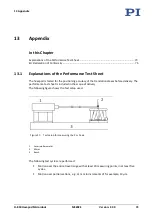
Страница 77: ...the translational axes before delivery The performance test sheet is included in the scope of delivery The following figure shows the test setup used Figure 21 Test setup for measuring the X or Y axis 1 Laser interferometer 2 Mirror 3 Bench The following test cycles are performed Motion over the entire travel range with at least 20 measuring points in at least five cycles Motion over partial secti...

Страница 78: ......

Страница 79: ...ration of Conformity For the H 850 an EU Declaration of Conformity has been issued in accordance with the following European directives EMC Directive RoHS Directive The applied standards certifying the conformity are listed below EMC EN 61326 1 Safety EN 61010 1 RoHS EN 50581 ...

Отзывы: