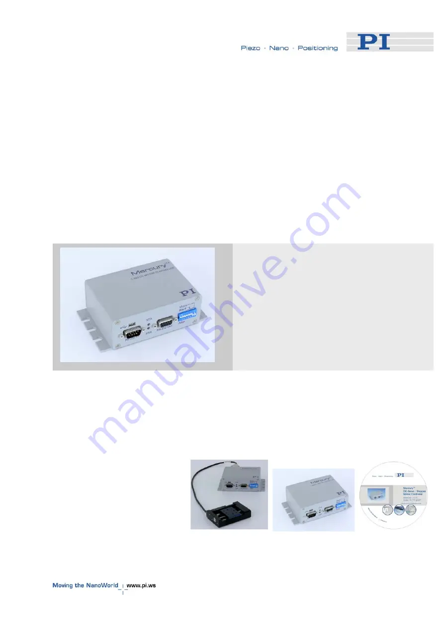
Physik Instrumente C-863 Mercury Скачать руководство пользователя страница 1

MS173E   User Manual 

C-863 Mercury™


DC Motor Controller


Release: 1.2.7 

Date: 2008-04-24 

This document describes the  
following product: 

„


C-863 

DC Motor Controller, Single-Axis, Networkable 


© Physik Instrumente (PI) GmbH & Co. KG


Auf der Roemerstr. 1 

 76228 Karlsruhe, Germany 


Tel. +49 721 4846-0 

 Fax: +49 721 4846-299 

 [email protected] 

 www.pi.ws 

Содержание C-863 Mercury

Страница 1: ...ease 1 2 7 Date 2008 04 24 This document describes the following product C 863 DC Motor Controller Single Axis Networkable Physik Instrumente PI GmbH Co KG Auf der Roemerstr 1 76228 Karlsruhe Germany Tel 49 721 4846 0 Fax 49 721 4846 299 info pi ws www pi ws ...

Страница 2: ... GmbH Co KG Karlsruhe Germany The text photographs and drawings in this manual enjoy copyright protection With regard thereto Physik Instrumente PI GmbH Co KG reserves all rights Use of said text photographs and drawings is permitted only in part and only upon citation of the source Document Number MS173E Release 1 2 7 C 863_User_MS173E127 doc Subject to change without notice This manual is supers...

Страница 3: ...oduct Product Name Single Channel DC Motor Controller Model Numbers C 863 Product Options all complies with the following European directives 2006 95 EC Low voltage directive LVD 2004 108 EC EMC Directive The applied standards certifying the conformity are listed below Electromagnetic Emission EN 61000 6 3 EN 55011 Electromagnetic Immunity EN 61000 6 1 Safety Low Voltage Directive EN 61010 1 April...

Страница 4: ...d result in injury or death CAUTION Calls attention to a procedure practice or condition which if not correctly performed or adhered to could result in damage to equipment NOTE Provides additional information or application hints Related Documents The software tools and any stages which might be delivered with C 863 DC Motor Controller are described in their own manuals All documents are available...

Страница 5: ... 232 from Host 13 2 2 2 USB from Host 13 2 3 Software Installation 13 2 3 1 USB Driver 14 2 3 2 GCS Software 14 2 3 3 Native Command Software 14 2 4 Starting Operation 15 3 System Description 19 3 1 Control of Multiple Axes 19 3 2 LED Status Indicators 19 3 3 Power up Settings 20 3 4 Cable Connections 20 3 5 Limit Signals 21 3 6 Reference Signal 22 3 7 Input Output Lines 22 3 8 DIP Switch Settings...

Страница 6: ...nsions 34 7 3 Connector Pinouts 35 7 3 1 Motor Connector 35 7 3 2 I O Connector 36 7 3 3 Joystick Connector 36 7 3 4 Joystick Y cable 37 7 3 5 RS 232 Connectors 37 7 3 6 USB Connector 38 7 3 7 Power Connector Grounding Screw 39 8 Disposal 40 www pi ws C 863 MS173E Release 1 2 7 Page 2 ...

Страница 7: ...ability Network Capability for Multi Axis Applications Compatible and Networkable with all other Mercury Class controllers including Mercury Step Joystick Port for Manual Control Non Volatile Macro Memory Parameter Changes on the fly Fig 1 C 863 10 Mercury Controller TTL Inputs for Limit Origin Switches Motor Brake Control Programmable I O Lines Multi Axis Control Combination of DC Stepper Motors ...

Страница 8: ...roller devices LabVIEW drivers and Windows DLLs allow for easy programming and integration into your system Mercury controllers can also be operated using the PI General Command Set GCS via a DLL PI GCS allows interoperation of different PI controllers such as piezo drivers and multi axis servo controllers with minimal programming effort 1 2 Prescribed Use Based on its design and realization the C...

Страница 9: ...d to accidents causing bodily injury damage to equipment or loss of warranty protection Note that the C 863 does not contain any user serviceable parts WARNING All motion of the connected motors and mechanical stages is software controlled and software may fail Be aware that motorized stages generate large forces that may cause personal injury or other damage if mishandled CAUTION Install and oper...

Страница 10: ...ard power supply for the Mercury and a motor that connects to these lines i e without separate PWM amplifier make sure the motor s operating voltage will not be exceeded CAUTION Never connect the RS 232 IN and USB connectors of the same controller to a PC at the same time as damage may result CAUTION Maintain Compliance Because the unit is not grounded over the power supply a grounding screw is pr...

Страница 11: ... User Manual this document in printed form If parts are missing or you notice signs of damage contact PI immediately Save all packing materials in case the product need be shipped again 1 5 Accessories The following items are not included but can be ordered separately Order Number C 815 38 Stage motor cable 3 m sub D 15 m f C 862 CN2 Long straight through networking cable for interconnecting Mercu...

Страница 12: ...rt is implemented by a Windows DLL which translates the GCS commands to the native commands for details see the Mercury GCS DLL manual MS154E The DLL has many command oriented functions making it unnecessary to generate the GCS commands as ASCII strings Most GCS commands and the corresponding DLL function calls are characterized by a three letter mnemonic NOTES Although the GCS DLL has a gateway f...

Страница 13: ... tasks for programmers of custom applications This DLL is based on the native command set See the Mercury Native DLL and LabView Manual MS177 for details LabVIEW VIs facilitate integrating Mercury class controllers in the LabVIEW environment Uses the native command MMC410 DLL above See the Mercury Native DLL and LabView Manual MS177 for details GCS Based Software PIMikroMove application for Micros...

Страница 14: ... an intermediate layer providing easy access to the controller from Windows programs The use of the DLL and the functions it contains is described in a separate manual MS154E Most of the DLL functions correspond directly with the commands of the PI General Command Set www pi ws C 863 MS173E Release 1 2 7 Page 10 ...

Страница 15: ... Element Type Purpose RS 232 In Sub D 9 m Command routing connects to PC or a networked Mercury class controller RS 232 Out Sub D 9 f Command routing in network connects to a networked Mercury class controller Mini B type USB Command routing connects to host PC do not connect when RS 232 IN is connected STA LED green Power and status ERR LED red green Command error green command OK red command err...

Страница 16: ... connector Supply power input center positive I O Mini DIN connector 9 pin Digital I O and analog input Joystick Mini DIN connector 6 pin Analog joystick input DC Motor only Sub D 15 f Motor stage connection I O DC motor only Screw washer Protective ground connection CAUTION Never connect a stepper motor drive to a C 863 DC motor controller Irreparable damage could result 2 2 Connecting Mercurys w...

Страница 17: ...ost computer 2 2 2 USB from Host When you connect via the USB interface for the first time be sure you are logged on the PC as a user having administrator rights After the C 863 is powered up a message will appear saying that new hardware has been detected Follow the on screen instructions and show the Hardware Wizard the USB_Driver directory on the Mercury CD NOTE The USB drivers will make the US...

Страница 18: ...nd PIMikroMove Typical is recommended 2 3 3 Native Command Software The Windows Setup routine can also be used to install the native command based software Setup puts it in subdirectories of the installation directory and adds the MMCRun and the Mercury firmware update programs to the PI program group under Start Programs PI Mercury If using only the native command software it is possible to bypas...

Страница 19: ...e the same as that assumed by the host software CAUTION Never connect a stepper motor drive to a C 863 DC motor controller Irreparable damage could result CAUTION The voltage output on the Motor and Motor pins can be as high as the supply voltage used If using a non standard power supply for the Mercury and a motor that connects to these lines i e without separate PWM amplifier make sure the motor...

Страница 20: ...ion are given in the respective software manual NOTE A USB connection will appear as an extra COM port when the controller is connected powered up and the USB drivers are installed The baud rate used by the host must be the same as that set on the DIP switches even if the USB interface is used Fig 4 PIMikroMove Start up Controller screen Step 1 with extra COM port for USB connection being selected...

Страница 21: ...ontroller Step 3 Reference the axis 8 After communication has been established make sure the motion parameters of each axis are set as required for the mechanics Starting parameters will be set if the software was informed of the type or class of stage connected as in Fig 5 Otherwise it may be necessary to set the www pi ws C 863 MS173E Release 1 2 7 Page 17 ...

Страница 22: ...the absolute position of each axis i e that the axis is referenced If the software did not prompt for referencing as in Fig 6 it may be assuming that the current position is 0 Arrange for the axis to move toward and stop at a limit or reference switch See the respective software or commands manual for details www pi ws C 863 MS173E Release 1 2 7 Page 18 ...

Страница 23: ...ed to commands in the native command set and the proper controllers are selected using the native addressing mechanism with its address selection codes All controllers connected can execute individual macro commands at the same time but there is no direct communication from controller to controller only from controller to the PC The host program must handle address selection and motion sequencing ...

Страница 24: ...troller Macro 0 can be used to set them It is not possible to store modified parameters as new power up defaults directly 3 4 Cable Connections The motor control signals are all on the 15 pin sub D DC Motor connector they include the motor control lines outputs and the encoder and limit switch signals inputs This connector is compatible with all PI stages having DC motors and current voice coil dr...

Страница 25: ...o stop motion at the end of the allowable travel range and or to provide absolute position information referencing see the commands manual for the command set you are using for details of commands that use these signals Each of the two switches will interrupt motion in a particular direction If positioning equipment from PI is used the limit switches or sensors are pre wired for operation with Mer...

Страница 26: ... high when the axis position is on one side of the reference position and low when the position is on the other side See the Commands manual for the command set you are using for a details of commands which can use the reference signal 3 7 Input Output Lines C 863 Mercury controllers offer 4 digital outputs and 4 inputs for either digital or analog 8 bit resolution use see p 36 for pinout of the I...

Страница 27: ...11 OFF ON OFF OFF 13 12 OFF OFF ON ON 14 13 OFF OFF ON OFF 15 14 OFF OFF OFF ON 16 15 OFF OFF OFF OFF Baud rate SW5 SW6 9600 ON ON 19200 OFF ON Other settings are fixed at 8 data and 1 stop bit no parity Internal buffers are used so there is no handshake required MMCRun supports only 9600 baud HW Limit Switch Mode SW7 Limits active low ON Limits active high OFF Hardware limit switch mode must agre...

Страница 28: ...ia RS 232 use of the USB interface is not recommended 2 Set DIP switch 8 to ON firmware update mode and power cycle the device both LEDs will remain dark 3 In Windows Explorer go to a directory on the harddrive containing both the MMC_update program executable and the new firmware image if necessary create it and copy the files there 4 Make sure the new firmware image filename begins with C863 and...

Страница 29: ..._update with the correct firmware type Fig 10 MMC_update main screen with C 863 tab and Start Update button circled 9 Make sure the C 863 tab card is on top 10 Make sure the proper firmware file is selected in the C 863 Firmware select pane There is a radio button there for each file in the same directory as the MMC_update executable that begins with C663 and has the hex extension www pi ws C 863 ...

Страница 30: ... from host PC serial port to RS 232 in of the Mercury to be updated Mercury not powered up Connect to power More than one instance of MMC_update running on the same COM port Close all instances and reopen a single instance note that minimized instances may dock themselves to a corner of the desktop Can not detect baud rate Verify switch 8 ON Another program has control of the COM port exit the oth...

Страница 31: ...ystick power is taken from the X axis branch so it must be connected to a powered up controller When a joystick is connected directly to the controller not to the host PC it is the velocity not the position or motion of the target of the controlled axes that is determined by the joystick position For use of the joystick on the host PC see the corresponding software manual e g SM148 for PIMikroMove...

Страница 32: ... one axis and the states of that axis buttons Fig 11 C 819 20 Joystick for Mercury Controllers 4 2 Pushbuttons The C 170 PB pushbutton box connects to the Mercury I O connector It allows applying TTL signals to the input lines and displays the state of the output lines on LEDs Fig 12 C 170 PB Pushbutton box with LEDs for Mercury Controllers www pi ws C 863 MS173E Release 1 2 7 Page 28 ...

Страница 33: ...g for details Examples of what is possible with an autostart macro sequence and a pushbutton box and or joystick to make the Mercury a stand alone controller under operator control include the following Execute commands that set proper operating parameters Execute motion commands Execute commands that wait for motion to complete Light one or more LEDs Execute a command or macro conditionally depen...

Страница 34: ...cause The autostart macro is active Solution Erase the autostart macro Joystick is connected but not calibrated See Section 4 on p 27 for details Joystick was activated but no joystick is connected Disable joystick Problem 3 When the PI host software starts no communication with the Mercury can be established Error message No controller found or Could not connect Solution Make sure that COM port i...

Страница 35: ...thout a physical brake deactivate the motor when the brake signal is in the default ON state Verify that the limit switch polarity and stage has limit switches axis parameters depends on stage type are set properly in native command set commands Lx in GCS SPA Verify that the hardware interlock limit switch polarity is properly set DIP switch 7 OFF for active high for standard PI DC motor drives Pr...

Страница 36: ...mit signal input e g insufficient source or sink current Contact PI and stage manufacturer to determine where the problem lies Verify that the hardware interlock limit switch polarity is properly set DIP switch 7 OFF for active high for standard PI DC motor drives Problem 8 The stage does not react to joystick motions Solution Make sure that the joystick is properly connected and enabled A joystic...

Страница 37: ...t power 3 A x supply voltage or as limited by power supply 30 W with standard 15 V 2 A C 890 PS Output voltage 0 to supply voltage 15 V with standard C 890 PS motor used must be compatible with supply voltage Interfaces and operation Communication interfaces RS 232 bus architecture USB Motor connector Sub D 15 f Controller network Up to 16 units on single interface I O lines 4 analog digital in 4 ...

Страница 38: ...oltage 15 to 30 VDC 15 V recommended if higher voltage used connected motor must be compatible Current draw 80 mA motor current 3 A max Operating temperature range 5 to 50 C Mass 0 3 kg Dimensions 130 x 76 x 40 mm 7 2 Dimensions Fig 13 C 863 dimensions in millimeters www pi ws C 863 MS173E Release 1 2 7 Page 34 ...

Страница 39: ...imit signal input 13 Reference signal input 6 Limit GND 14 Encoder A ENCA input 7 Encoder A input 15 Encoder B ENCB input 8 Encoder B input PWM pulse width modulation ON voltage magnitude on these lines is close to the supply voltage CAUTION The voltage output on the Motor and Motor pins can be as high as the supply voltage used If using a non standard power supply for the Mercury and a motor that...

Страница 40: ...output Output 1 digital TTL 6 output Output 2 digital TTL 7 output Output 3 digital TTL 8 output Output 4 digital TTL 9 output Vcc 5V Fig 15 Mini DIN 9 pin I O connector 7 3 3 Joystick Connector Pin Signal direction Function 1 GND 2 n c 3 output Vcc 3 3 V 4 input Input Joystick analog 0 to 3 3 V 5 n c 6 input Input Joystick Button 1 Fig 16 Mini DIN 6 pin PS2 style joystick connector www pi ws C 86...

Страница 41: ...9 20Y joystick Y cable with 2 controllers 7 3 5 RS 232 Connectors Connector Labels RS 232 IN and RS 232 OUT Connector Types Sub D 9 pin male for OUT female for IN The IN and OUT lines are permanently bussed together straight through Only when the USB interface is active does the controller assert signals on the RxD receive line pin 2 otherwise that line is driven by the host PC only This is the re...

Страница 42: ...de are reversed If the PC connection is via USB then the Mercury connected to the PC copies everything received from the host over USB to the Mercury RxD line of both its RS 232 connectors It also copies everything it sees on the Mercury TxD line to the host via USB CAUTION Never connect the RS 232 IN and USB connectors of the same controller to a PC at the same time as damage may result www pi ws...

Страница 43: ...tside input Power GND Grounding screw lower left Protective ground CAUTION Maintain Compliance Because the unit is not grounded over the power supply a grounding screw is provided at the lower left corner of the rear panel for connecting the metal case to a protective ground Connection to a protective ground is required for compliance with applicable directives www pi ws C 863 MS173E Release 1 2 7...

Страница 44: ...ith other wastes To meet the manufacturer s product responsibility with regard to this product Physik Instrumente PI GmbH Co KG will ensure environmentally correct disposal of old PI equipment that was first put into circulation after 13 August 2005 free of charge If you have such old equipment from PI you can send it to the following address postage free Physik Instrumente PI GmbH Co KG Auf der R...

Отзывы: