FASTCAM-512PCI Hardware Manual
- 12 -
1
2
3
4
O
N
ディップスイッチ
1.4.1. Master/Slave Mode Setup
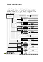
For multiple-camera synchronized operation, one of the cameras must be set up as the master
camera and the other cameras set up as slaves. With cameras set up in this way, the slaves
operate following the sync signal provided by the master. As a result, all the cameras record
images in a shared timeline.
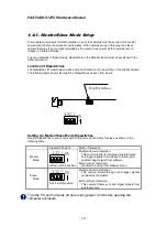
To set up cameras in these modes, dipswitches on the Grabber Board must be positioned in the
following manner:
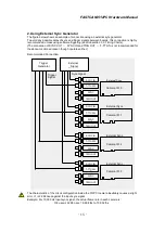
Location of Dipswitches
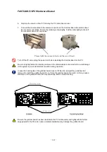
The dipswitches for master/slave mode setup are located on the top surface of the Grabber Board.
The following figure shows the location of dipswitches as seen from above.
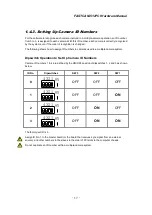
Setting Up Master/Slave Mode Dipswitches
Operate dipswitches to set up one board for master and the others for slave as shown in the
following table.
Dipswitch Position
Mode of Operation
Master
Mode
1
2
3
4
O
N
All four in OFF position
Multiple-Camera Operation:
This camera feeds its internally generated sync
and trigger signals to the slaves to follow, and
enables trigger signal from software.
External Sync Operation:
Disables the setup from software menu.
Slave
Mode
1
2
3
4
O
N
SW 4 in ON position
Multiple-Camera Operation:
This camera follows the sync and trigger signals
provided by the master.
External Sync Operation:
This camera follows sync and trigger signals from
external source.
Turn the PC and cameras off and unplug power cord before opening the
computer enclosure
Dip Switches
Содержание FASTCAM-512 PCI
Страница 1: ...FASTCAM 512PCI Hardware Manual Rev 1 06E...
Страница 32: ...FASTCAM 512PCI Hardware Manual 24 Memo...
Страница 33: ...FASTCAM 512PCI Hardware Manual 25 Chapter 2 Appendix 2 1 Specifications 2 2 Dimensions 2 3 Timing Charts...
Страница 45: ...FASTCAM 512PCI Hardware Manual 37 2 2 Dimensions 2 2 1 Camera Head Millimeters 64 2 8 2 56 85 85...
Страница 53: ...FASTCAM 512PCI Hardware Manual 45 Chapter 3 Contacting Photron 3 1 Contact Information...


