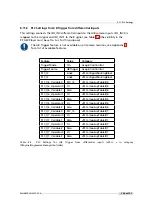
8.11 PLC Settings
8.11
PLC Settings
8.11.1
Introduction
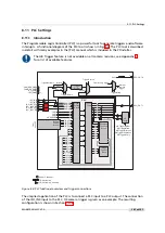
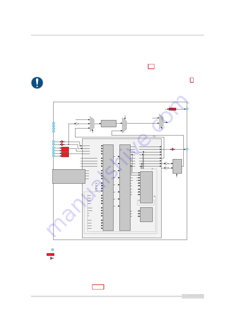
The Programmable Logic Controller (PLC) is a powerful tool to generate triggers and software
interrupts. A functional diagram of the PLC tool is shown in Fig. 8.4. The PLC tool is described
in detail with many examples in the [PLC] manual which is included in the PFInstaller.
The AB Trigger feature is not available on all camera revisions, see Appendix B
for a list of available features.
A
0 ( L i n e 0 )
A 1 ( L i n e 1 )
S i g n a l
R o u t i n g
B l o c k
A 4
A 5
A 6
A 7
P
L C
7
I S O _ I N 0
9
I S O _ I N 1
I S O _ I N C 0 _ P
5
4
I S O _ I N C 0 _ N
I S O _ I N C 1 _ P
1 1
1 0
I S O _ I N C 1 _ N
P o w e r C o n n e c t o r
I / O d e c o u p l i n g
F V A L
L V A L
D V A L
R E S E R V E D
P L C _ c t r l 0
P L C _ c t r l 1
P L C _ c t r l 2
P L C _ c t r l 3
Q 2
Q 3
Q 6
Q 7
p g 0 _ o u t
p g 1 _ o u t
p g 2 _ o u t
p g 3 _ o u t
d e l _ o u t
r s l _ o u t
g p _ c n t _ e q
g p _ c n t _ g t
t s _ t r i g 0
t s _ t r i g 1
t s _ t r i g 2
t s _ t r i g 3
L o o k u p
T a b l e
I 1
I 2
I 3
I 4
I 5
I 6
I 7
I 0
E n h a n c e d
F u n c t i o n
B l o c k
Q 0
Q 1
Q 2
Q 3
Q 4
Q 5
Q 6
Q 7
Q 8
Q 9
Q 1 0
Q 1 1
Q 1 5
Q 1 6
Q 1 7
R e m o t e
C o n t r o l
B l o c k
fr
o
m
h
o
s
t
P
C
8
I S O _ O U T 1
I m a g e
C o n t r o l
B l o c k
Q 1 2
Q 1 3
Q 1 4
T r i g g e r S o f t w a r e
T r i g g e r S o u r c e
F r e e - r u n n i n g t r i g g e r
I n t e r n a l
c a m e r a
t r i g g e r
T r i g g e r M o d e
3
I S O _ O U T 0
S t r o b e
A 2 ( L i n e 2 )
A 3 ( L i n e 3 )
L i n e 1
P L C _ Q 4
S o f t w a r e
O f f
O n
1
C A M E R A _ G N D
2
C A M E R A _ P W
R
6
I S O _ P W
R
1 2
I S O _ G N D
I / O d e c o u p l i n g , i n v e r t i n g
T r i g g e r
D i v i d e r
A B
T r i g g e r
A
B
A B T r i g g e r D i v i d e r
A B T r i g g e r M o d e
A B T r i g g e r D i r e c t i o n
A B T r i g g e r D e b o u n c e
A B T r i g g e r A O n l y
A B T r i g g e r
T r i g g e r S o u r c e
Figure 8.4: PLC functional overview and trigger connections
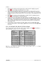
The simpliest application of the PLC is to connect a PLC input to a PLC output. The connection
of the ISO_IN0 input to the PLC_Q4 camera trigger is given as an example. The resulting
configuration is shown in Section 8.11.2.
MAN075 05/2017 V1.0
107 of 127
Содержание MV1-D2048-3D06 series
Страница 1: ...Photonfocus MV1 D2048 3D06 Camera Series 3D CMOS camera with GigE interface MAN075 05 2017 V1 0...
Страница 10: ...1 Preface 10 of 127 MAN075 05 2017 V1 0...
Страница 12: ...2 Introduction 12 of 127 MAN075 05 2017 V1 0...
Страница 16: ...3 How to get started 3D GigE G2 Figure 3 3 PFInstaller components choice 16 of 127 MAN075 05 2017 V1 0...
Страница 26: ...3 How to get started 3D GigE G2 26 of 127 MAN075 05 2017 V1 0...
Страница 32: ...4 Product Specification 32 of 127 MAN075 05 2017 V1 0...
Страница 66: ...5 Functionality 66 of 127 MAN075 05 2017 V1 0...
Страница 82: ...6 Precautions 82 of 127 MAN075 05 2017 V1 0...
Страница 120: ...12 Support and Repair 120 of 127 MAN075 05 2017 V1 0...
Страница 122: ...13 References 122 of 127 MAN075 05 2017 V1 0...
Страница 127: ...C Revision History Revision Date Changes 1 0 May 2017 First version MAN075 05 2017 V1 0 127 of 127...


