

4
Sound Field System User Instructions
• Switch the receiver POWER control on.
The receiver is now ready to receive the
FM signal from the transmitter. The ON
and NO FM lights will be on.
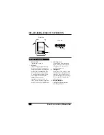
U
SING THE
T
RANSMITTER
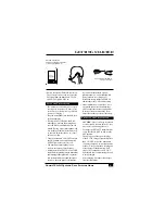
The transmitter will need to be charged
overnight or for at least 12 hours prior
to the first use. (Batteries are protected
from over-charging.)
• Plug the microphone into the MIC jack
of the transmitter.
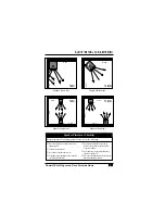
• If using the AT655 Behind-the-Neck
microphone, position the microphone
over the left ear and slightly below the
mouth. If using a lapel microphone, clip
it to clothing or adjust the lavalier cord
so that it is no further than 6 in (15cm)
below your chin.
• Turn the transmitter’s ON/OFF switch to
the ON position, and verify that the red
NO FM light on the receiver is off.
• The transmitter/microphone is now
ready to accept your speech signal.
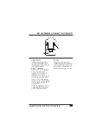
• Adjust the receiver’s FM VOL and TONE
controls while speaking into the transmitter
and listening to the speakers. As a general
rule, increase treble in a sound-absorptive
room (i.e., one with carpet, soft furniture,
etc.), and decrease treble in a sound-
reflective room (i.e., one with hard walls,
floors, furniture, etc.). (See page 5.)
If feedback occurs, reduce the FM VOL
and/or reduce the TONE control setting.
• Make installation a team effort —have
one person speak into the transmitter
while another checks the sound quality
in various locations around the room.
Adjust the speaker position if necessary.
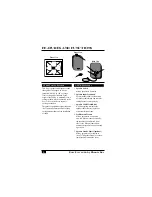
C
HARGING THE
T
RANSMITTER
CAUTION: Do not recharge disposable
or rechargeable alkaline batteries–they
may rupture and damage the unit.
• To charge the PE 300T Transmitter first
verify that the ON/OFF switch is in the
OFF position.
• Then, plug one of the two mini plugs
of the AT534 Charger/Transformer into
the AUX/CHG jack of the transmitter.
(You may charge up to two transmitters
at once.) Next, connect the wall plug end
of the Charger/Transformer to a wall
socket. The Transmitter’s AUX/CHG
light should come on indicating the unit
is being charged.
• After charging, disconnect the charger
from the transmitter.
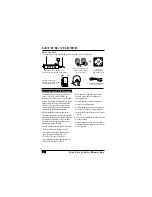
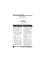
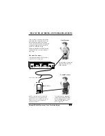
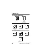
GETTING STARTED
AT534 Wall Transformer/
Two-Unit Charger
PE 300T Transmitter
with AT655 BTN Microphone
or other appropriate mic


