Phoenix Geophysics MTU-5D Скачать руководство пользователя страница 8

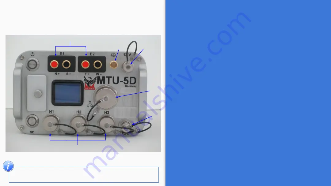
Start by connecting:

1.

Ground electrode

2.

Electrodes  to  channel

  E1

(Ex)  (N+,  S-)  and 

channel 

E2

(Ey) (E+, W-)

3.

Magnetic  sensors  to  channels 

H1

(Hx)

,  H2

(Hy) 

and 

H3

(Hz)

4.

GPS antenna

5.

12V DC Power Source

6.

Network connector

5

1

2

4

3

In the field, it is often most efficient to connect the 
components to the receiver following the order on the right

MTU-5D

Connections

6

8

Содержание MTU-5D

Страница 1: ...guration Creator 5 Electric Channel Settings 6 Magnetic Channel Settings 7 Saving a Configuration File 8 MTU 5D Connections 9 SD Card Recording Data 10 Stopping a recording 11 Importing and Evaluating Data 12 Evaluate 13 Process Data 14 View Recording Details 1 Version 200914 ID DAA20 ...

Страница 2: ...Ey electrode connectors 4 Ground electrode connector 5 12VDC power input 6 LAN connector 7 GPS antenna connector 8 H1 Hx magnetic sensor connector H2 Hy magnetic sensor connector H3 Hz magnetic sensor connector 9 SD card button and indicator 10 SD card slot and cover 5 4 3 6 1 9 7 8 2 10 2 ...

Страница 3: ...re button Complete the required information 1 Select the Receiver Type 2 Recording 2 1 MT Configuration Creator 3 Calibration 3 1 Sensor Calibration 3 2 Receiver Calibration No additional configuration needed 4 System tests 4 1 White Noise 4 2 Parallel Noise Configuration Creator 4 3 Self Test No additional configuration needed 3 ...

Страница 4: ...e use Single Shot Daily or Weekly and click Add Schedule to define the time and date 3 Channels Settings 4 Define the Receiver Settings Sampling Mode and or Sampling Rate 5 Configuration Layout 5 Additional information 3 2 2 2 2 1 4 1 4 This section is used for inputting the parameters and instrument details that will be used for the recording ...

Страница 5: ...r Disable the channel s Disable the channel s If you do not plan to use them during the recording This will save space on the SD card 3 Complete the information in the Electric channel settings 2 Channel settings can be configured by using the right click menu 5 1 2 3 ...

Страница 6: ... to use them during the recording This will save space on the SD card 3 Fill in the required information on the Magnetic channel settings 2 Channel settings can be configured by using the right click menu or by using the Magnetic channel settings section 6 1 3 2 Some channel settings can be configured by using the right click menu ...

Страница 7: ...ill automatically create the file config json 3 Save the configuration file config json in the root folder of the SD card 4 Open the file Explorer Right click SD card drive Select Eject option Pull out the SD Card Only SD cards supplied by Phoenix are supported Other SD cards that comply with the SDXC standard may work depending on the card rating and environmental conditions 7 ...

Страница 8: ...d channel E2 Ey E W 3 Magnetic sensors to channels H1 Hx H2 Hy and H3 Hz 4 GPS antenna 5 12V DC Power Source 6 Network connector 5 1 2 4 3 In the field it is often most efficient to connect the components to the receiver following the order on the right MTU 5D Connections 6 8 ...

Страница 9: ... the Troubleshooting manual 3 If the schedule type was configured as Manual press the Power button to start recording Press the power button briefly and release Starting Acquiring GPS Ready SD 2 3 Press the power button briefly and release Ready Channels Recording Detection SD Automatic Start The recording starts automatically according to the schedule Recording SD 2 1 2 2 Indicators Rapid equal p...

Страница 10: ...ng the Power button for a few seconds the LEDs will flash red Wait until both LEDs turn off 3 Eject the SD card Press the SD card and release pull the SD card Rapid equal pulses Solid color Off Indicators Keep pressing the power button 3 sec and release Ready Shutdown Off SD 1 2 Press the Power button briefly and release Recording Saving Ready SD 3 10 ...

Страница 11: ... button 2 Select View data 3 Select the SD card The recording creates two folders log and recdata 4 Open the recdata folder and select the recording folder and click Choose Receiver Serial Number Recording Date Recording Start Time GPS time 2 1 3 4 11 ...

Страница 12: ...cted and make the necessary corrections Serial Polarity H1 H 3 Azimuth 3 View Recording Details see page 14 4 Process the recorded data after the reviewed the information see next page Evaluate 4 The warning icon indicates that something might be wrong with the recording review the recording information and make necessary changes 2 1 This section can also be used to input additional field informat...

Страница 13: ...od by entering a start and end date time 3 Enable the electric power grid filter that corresponds to the frequency carried by the power lines in the survey region 50Hz 60Hz or None 4 Click the Process button 5 A live display of the resistivity curve will appear after a few seconds This resistivity curve is not saved It is purely for QC purposes ...

Страница 14: ...its for quality control 1 Battery Voltage 2 Internal Temperature 3 Number of Satellites 4 Saturated Frames If saturation is not close to 0 review the channel configuration see pages 4 6 the channel gain might be too high and or there is artificial noise on your site 5 Time Series Level 14 ...

Отзывы: