
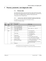


Startup
109745_en_01
PHOENIX CONTACT
35 / 66
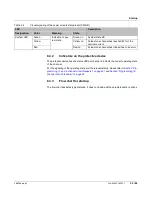
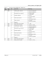
6.3.2
Indicators on the protective device
The protective device has one status LED per channel to indicate the current operating state
of the channel.
For the signaling of the operating state and the relevant status, please refer to
gramming (1- and 4-channel circuit breakers)” on page 31
channel circuit breakers)” on page 32
.
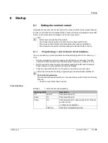
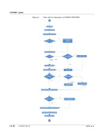
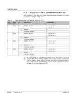
6.3.3
Flow chart for startup
The flow chart illustrates typical startup. It does not include all the parameterization options.
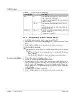
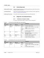
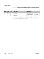
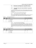
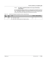
System LED
Green
Indication of sys
-
tem state
Green on
System state OK
Yellow
Yellow on
At least one channel has reached 80% of the
nominal current
Red
Red on
At least one channel has tripped due to an error
Table 6
-
4
Visual signaling of the power module status-reset (PM S-R)
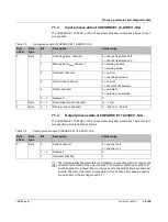
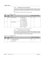
LED
Description
Designation
Color
Meaning
State
Содержание 1110984
Страница 1: ...User manual CAPAROC System and installation...
Страница 20: ...CAPAROC system 20 66 PHOENIX CONTACT 109745_en_01...
Страница 22: ...CAPAROC system 22 66 PHOENIX CONTACT 109745_en_01...
Страница 28: ...CAPAROC system 28 66 PHOENIX CONTACT 109745_en_01...
Страница 52: ...CAPAROC system 52 66 PHOENIX CONTACT 109745_en_01...
Страница 54: ...CAPAROC system 54 66 PHOENIX CONTACT 109745_en_01 Figure 8 1 PC WORX FIRMWARE UPDATER...
Страница 67: ......