Service Modes, Error Codes, and Fault Finding
5.
5.
Service Modes, Error Codes, and Fault Finding
Index of this chapter:
5.1 Service Mode
5.2 Error Codes
5.3 Fault Finding and Repair Tips
5.1
Service Mode
The Service Mode is activated by pressing ‘1923’ on the
Remote Control, while the set is in the Main User Menu.
The software provides menu flexibility and full control to the
software. Service persons can adjust the TV in all manners. In
the Service Menu (see chapter 8), you find a list of parameters.
All functions of the Service Mode, and the default parameter
settings, are listed in Chapter “Alignments”.
5.2
Error Codes
These sets do not generate Error Codes.
5.3
Fault Finding and Repair Tips
Notes:
•
It is assumed that the components are mounted correctly
with correct values and no bad solder joints.
•
Before any fault finding actions, check if the correct options
are set.
•
The Service Menu (see chapter 8), contains some useful
tests, that generates patterns.
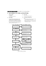
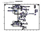
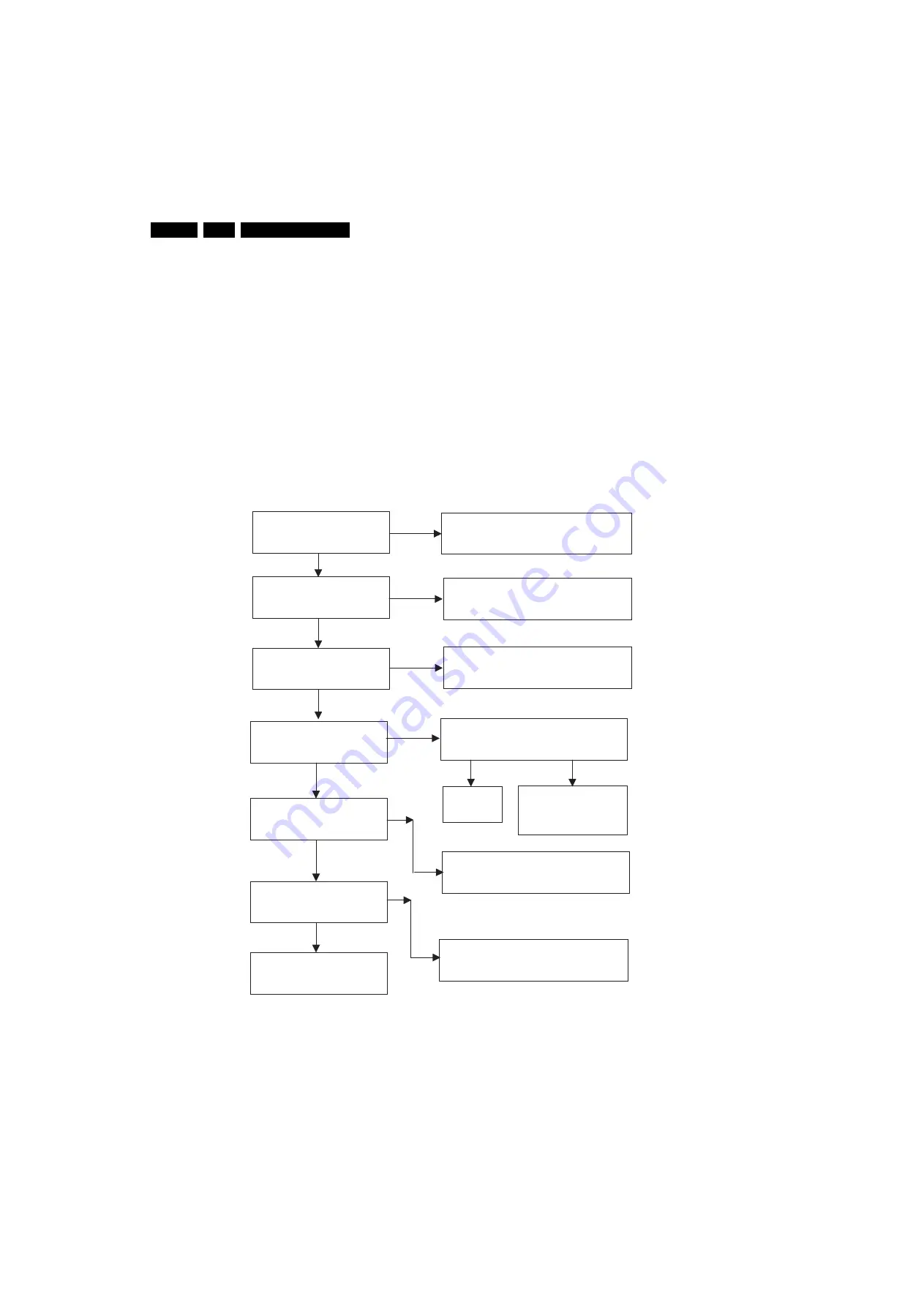
Figure 5-1 Fault finding power supply
FAULT TRACING DIAGRAM FOR POWER SUPPLY
Check 220 V AC Mains
Check C 020 Voltage
Check 5VSTBY
Check 5V_OFF
Check 24V,33V,12V
8V
Check 3.3V,2.5V and 1.8V
POWER IS OK
NO
NO
NO
NO
NO
Check AC Power Cable is Plugged
Check X102 Fuse
Check T530 and Peripheral
Components
Check P_CTRL Pin
Check Related Components
StandBy
Mode
Normal Mode
Check Components
For 5V
Check Related Components for
Defective Outputs
YES
YES
YES
LOW
HIGH
YES
NO
YES
YES
H_17490_017.ep
s
291007
Содержание TES2.0E
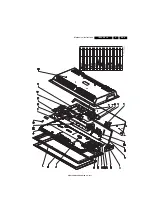
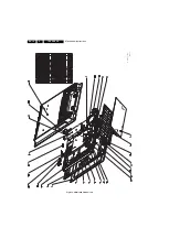
Страница 9: ...Mechanical Instructions EN 9 TES2 0E LA 4 Figure 4 3 Exploded View 32 sets H_17490_015 eps 291007 ...
Страница 10: ...Mechanical Instructions EN 10 TES2 0E LA 4 Figure 4 4 Exploded View 42 sets H_17490_016 eps 291007 ...
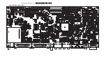
Страница 26: ...EN 26 TES2 0E LA 7 Circuit Diagrams and PWB Layouts Layout Main Board Top Side H_17490_009 eps 161007 ...


