


5
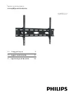
3 Installing your wall mount
In this chapter, the basic steps to get you started
are described.
B
Warning
Carefully read the safety precautions
in “Section Important” before you
install the wall mount.
3. Mounting the wall plate (drywall)
B
Warning
For safety reasons, this mount must
be secured to three adjacent wood
studs at least 6” apart. The studs
must be capable of supporting the
combined weight of the mount and
display.
1
See enclosed mounting template for
diagram and guide of how to mount
properly on the wall.
2
Using a stud finder, locate and mark three
adjacent studs for securing the mount
(make sure your marks are in the center
of each stud). You can use your own stud
finder or the one included in the hardware
kit.
D
Note
Once studs have been located you will
need to verify with a hammer and a
nail
A) Simply place the nail over your
mark on the wall and tap in with
hammer. If the nail encounters
resistance and is secure in wall you
have verified a stud location
B) If it just pushes through with no
resistance you will need to start
over and locate the stud.
3
Using the enclosed mounting template,
place the diagram against the wall and mark
six locations (two per stud) on the wall
where the mount Is to be Installed. Be sure
to use the center of each stud.
4
With the help of another person, place the
mount against the wall and level it using the
bubble guide.
5
While another person holds the mount in
place, mark six locations (two per stud) on
the wall where the mount is to be installed.
Be sure to use the center of each stud.
(these marks should line up with the ones
made in step 3 above using the template).
6
Set the mount aside and drill a 1/4” (6 mm)
pilot hole at each marked location.
7
Place the mount back against the wall and
secure it using the lag bolts (Q) and lag bolt
washers (R) provided. Do not over-tighten
these bolts and do not release the mount
until all bolts are in place.
8
Once all (6) lag bolts are in place you must
tighten each one. Be sure not to over
tighten.
1
1
3. Mounting the wall plate (concrete)
B
Warning
For safety reasons, the concrete wall
must be capable of supporting the
combined weight of the mount and
display.
1
See enclosed mounting template for
diagram and guide of how to mount
properly on the wall.
2
Using the enclosed mounting template,
place the diagram against the wall and mark
six locations on the wall where the mount
Is to be Installed.
3
With the help of another person, place the
mount against the wall and level it using the
bubble guide.
4
While another person holds the mount in
place, mark six locations on the wall where
Содержание SQM5322/27
Страница 23: ......
Страница 24: ... 2008 Koninklijke Philips Electronics All rights reserved ...