Philips SignageSolutions BDL5586XL Скачать руководство пользователя страница 17

BDL5586XL

9

3.  Connecting External Equipment

3.1.  Connecting External Equipment (DVD/VCR/VCD)

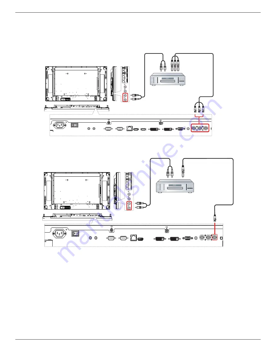
3.1.1.  Using COMPONENT video input

DVD / VCR / VCD

[AUDIO IN]

[COMPONENT IN]

(YPbPr)

COMPONENT Out
(YPbPr)

Audio Out

[R]

[L]

~

3.1.2.  Using Video Source input

DVD / VCR / VCD

[AUDIO IN]

[Y/CVBS IN]

Y/CVBS Out 

Audio Out

[R]

[L]

~

Содержание SignageSolutions BDL5586XL

Страница 1: ...www philips com welcome BDL5586XL User Manual English ...

Страница 2: ...block the ventilation holes on the cabinet Keep the display dry To avoid electric shock do not expose it to rain or excessive moisture If turning off the display by detaching the power cable wait for 6 seconds before re attaching the power cable for normal operation To avoid the risk of shock or permanent damage to the set do not expose the display to rain or excessive moisture When positioning th...

Страница 3: ...vide reasonable protection against harmful interference when the equipment is operated in a commercial environment This equipment generates uses and can radiate radio frequency energy and if not installed and used in accordance with the instructions manual may cause harmful interference to radio communications Operation of this equipment in a residential area is likely to cause harmful interferenc...

Страница 4: ...tandards PN 93 T 42107 and PN 89 E 06251 Electric Magnetic and Electronmagnetic Fields EMF 1 We manufacture and sell many products targeted at consumers which like any electronic apparatus in general have the ability to emit and receive electromagnetic signals 2 One of our leading Business Principles is to take all necessary health and safety measures for our products to comply with all applicable...

Страница 5: ...should not be greater than 5A NOTE The severed plug must be destroyed to avoid a possible shock hazard should it be inserted into a 13A socket elsewhere How to connect a plug The wires in the mains lead are coloured in accordance with the following code BLUE NEUTRAL N BROWN LIVE L GREEN YELLOW EARTH E 1 The GREEN YELLOW wire must be connected to the terminal in the plug which is marked with the le...

Страница 6: ...B 多溴二苯醚 PBDE 外壳 O O O O O O 液晶面板 X O O O O O 电路板组件 X O O O O O 附件 遥控器 电源线 连接线 X O O O O O 遥控器电池 X O O O O O O 表示该有毒有害物质在该部件所有均质材料中的含量均在 SJ T11363 2006 标准规定的限量要求以下 X 表示该有毒有害物质至少在该部件的某一均质材料中的含量超出 SJ T11363 2006 标准规定的限量要求 10 環保使用期限 此標識指期限 十年 電子信息產品中含有的有毒有害物質或元素在正常使用的條件下不會發生外泄或突變 電子信息產品用戶使用該電子信息產品不會對環境造成嚴重污染或對其人身 財產造成嚴重損害的期限 ...

Страница 7: ...cation Initiative Waste Electrical and Electronie Equipment WEEE Attention users in European Union private households This marking on the product or on its packaging illustrates that under European Directive 2002 96 EG governing used electrical and electronic appliances this product may not be disposed of with normal household waste You are responsible for disposal of this equipment through a desi...

Страница 8: ...s 30 1 Unpacking and Installation 1 1 1 Unpacking 1 1 2 Package Contents 1 1 3 Installation Notes 1 1 4 Installing and RemovingTable Stands optional 2 1 5 Mounting on a Wall 3 1 5 1 VESA Grid 3 1 6 Mounting in Portrait Position 4 2 Parts and Functions 5 2 1 Control Panel 5 2 2 Input OutputTerminals 6 2 3 Remote Control 7 2 3 1 General functions 7 2 3 2 Inserting the batteries in the remote control...

Страница 9: ...da Guide de démarrage rapide Guida rapida Instrukcja szybkiego uruchomienia Краткое руководство по запуску Hızlı bașlangiç kılavuzu 快速入门指南 快速入門指南 Installation Installation Instalación Installation Installazione Instalacja Установка Kurulum 安装 安裝 Connect Verbindungsfähigkeit Conectividad Connectivité Connettività Połączenia Подключение Bağlantı 连接性 連接性 BDL5586XL LCD Display Quick start guide IR Sen...

Страница 10: ...the stand in the guide block tighten the screws on both sides of the display NOTE The longer side of the stand should face the front of the display Carrying handle Thumbscrews Table stand Logoer portions face to front To remove table stands 1 Power off the display 2 Spread a protective sheet on a flat surface 3 Grab the carrying handles and place the display face down on the protective sheet 4 Rem...

Страница 11: ... the user or installer Product warranty does not cover damage caused by improper installation 4 For the wall mounting kit use M6 mounting screws having a length 10 mm longer than the thickness of the mounting bracket and tighten them securely 1 5 1 VESA Grid BDL5586XL 400 H x 400 V mm Caution To prevent the display from falling For wall or ceiling installation we recommend installing the display w...

Страница 12: ...unting in Portrait Position This display can be installed in portrait position 1 Remove the table stand if attached 2 Rotate 90 degrees anticlockwise The logo should be bristling when facing the display at the back 90 90 ...

Страница 13: ...d Control functions To enable or disable the keyboard control lock press both and buttons and hold down continuously for more than 3 three seconds 9 Remote control sensor and power status indicator Receives command signals from the remote control Indicates the operating status of the display without OPS Lights green when the display is turned on Lights red when the display is in standby mode Light...

Страница 14: ...ion 7 RJ 45 LAN control function for the use of remote control signal from control center 8 HDMI IN HDMI video audio input 9 DisplayPort DisplayPort video input 10 DVI IN DVI D video input 11 DVI OUT VGA OUT DVI orVGA video output 12 VGA IN D Sub VGA video input 13 VGA AUDIO IN Audio input forVGA source 3 5mm stereo phone 14 COMPONENT IN BNC ComponentYPbPr video source input 15 Y CVBS Video source...

Страница 15: ...D menu 8 AUTO ADJUST button Press to run the Auto Adjust function NOTE This button is functional for VGA input only 9 MUTE button Press to turn the mute function on off 10 VIDEO SOURCE button Press to toggleVideo Source Menu Press or button to select one of the video sources among Displayport DVI D VGA HDMI Component Video Card OPS Press SET button to confirm and exit 11 AUDIO SOURCE button Press ...

Страница 16: ...intend to use the remote control for a long period remove the batteries 2 3 3 Handling the remote control Do not subject to strong shock Do not allow water or other liquid to splash the remote control If the remote control gets wet wipe it dry immediately Avoid exposure to heat and steam Other than to install the batteries do not open the remote control 2 3 4 Operating range of the remote control ...

Страница 17: ...nt 3 1 Connecting External Equipment DVD VCR VCD 3 1 1 Using COMPONENT video input DVD VCR VCD AUDIO IN COMPONENT IN YPbPr COMPONENT Out YPbPr Audio Out R L 3 1 2 UsingVideo Source input DVD VCR VCD AUDIO IN Y CVBS IN Y CVBS Out Audio Out R L ...

Страница 18: ...BDL5586XL 10 3 1 3 Using HDMI video input DVD VCR VCD HDMI Out HDMI IN 3 2 Connecting a PC 3 2 1 UsingVGA input PC VGA IN VGA AUDIO IN VGA Out D Sub 15 pin Audio Out AUDIO IN R L ...

Страница 19: ...BDL5586XL 11 3 2 2 Using DVI input PC VGA AUDIO IN DVI Out Audio Out AUDIO IN R L DVI IN 3 2 3 Using HDMI input PC HDMI Out HDMI IN ...

Страница 20: ...sing DisplayPort input PC DisplayPort Out DisplayPort IN 3 3 Connecting Audio Equipment 3 3 1 Connecting external speakers External speakers 3 3 2 Connecting an external audio device Stereo Amplifier AUDIO OUT R L Audio In ...

Страница 21: ...U IR IN IR OUT 3 4 2 IR PassThrough Control To control aVideo Wall set up by multiple displays use the IR Sensor Cable and the IR Cable to achieve the function IR Sensor Cable IR input port of the DVD player Display IR IN IR OUT IR Cable Remote control of DVD player DVD Player 1 Connect the IR Sensor Cable to the IR IN port of the display 2 Connect with the IR Cable from the IR OUT port of the dis...

Страница 22: ...on Connect the RS232C OUT connector of DISPLAY 1 to the RS232C IN connector of DISPLAY 2 PC DISPLAY 2 DISPLAY 1 RS 232C IN RS 232C RS 232C OUT RS 232C IN 3 5 2 Digital video connection Connect the DVI OUT VGA OUT connector of DISPLAY 1 to the DVI IN connector of DISPLAY 2 PC DVI IN DVI DVI VGA OUT DVI IN DISPLAY 2 DISPLAY 1 3 5 3 Analog video connection Connect the DVI OUT VGA OUT connector of DIS...

Страница 23: ...ect the RS232C OUT connector of DISPLAY 1 to the RS232C IN connector of DISPLAY 2 DISPLAY 2 DISPLAY 1 RS 232C OUT IR Sensor Cable POWER SMART VIDEO SOURCE PIP INPUT ON OFF CHANGE BRIGHTNESS CONTRAST DISPLAY AUTO ADJUST MUTE VOL UP VOL DOWN EXIT MENU SET AUDIO SOURCE USB MENU RS 232C IN IR IN ...

Страница 24: ... Configuration2 Advanced option Noise reduction Brightness Adjust the overall image brightness by changing the intensity of the LCD panel s backlight Contrast Adjust to sharpen the picture quality The black portions of the picture become richer in darkness and the white become brighter Sharpness Adjust to improve the image detail Black level Video black level is defined as the level of brightness ...

Страница 25: ...f the image NOTE This item is functional for VGA input only Zoom mode The pictures you receive may be transmitted in 16 9 format wide screen or 4 3 format conventional screen The 16 9 pictures sometimes have a black band at the top and bottom of the screen letterbox format Zoom Mode will be deactivated when Pixel Shift is activated or turned on This function allows you to optimize the picture disp...

Страница 26: ...udio input source according to the audio signal source connected to the audio input and HDMI sockets on the display Choose from Displayport HDMI Audio1 Audio2 Card OPS Audio reset Reset all settings in the Audio menu to factory preset values Card OPS audio Select the analog or digital audio mode for card OPS 4 2 4 PIP menu PIP PIP input PIP change PIP size PIP reset Picture Screen Audio PIP Config...

Страница 27: ...elect On to let the display enter APM mode when no signal is detected from the HDMI Graphic mode HDMI DVI D or VGA inputs after three successive cycles VIDEO Select On to enter power saving mode when no signal is detected from the HDMIVideo mode orYPbPr inputs after three successive cycles Language Select the language used in the OSD menu The options are 简体中文 繁體中文 Panel saving Choose to enable the...

Страница 28: ...riod of time the OSD on screen display menu stays on the screen The options are 5 120 seconds Information OSD Set the period of time the information OSD is displayed on the upper right corner of the screen The information OSD will display when input signal is changed The information OSD will remain on the screen with Off selection The options are 1 60 seconds OffTimer Set the display to turn itsel...

Страница 29: ...increases the chance of image retention Film mode Choose to turn on or off the film mode frame conversion function Auto Enable the film mode frame conversion function for movies and motion pictures The display converts a 24 frames per second 24 fps input signal format to DVD video signal format Once this function is enabled it is recommended that you set the Scan conversion function to Progressive...

Страница 30: ...isabled when the ON OFF button for PIP is pressed Heat status This function allows you to check the thermal status of the display at any time Date and time Adjust the current date and time for the display s internal clock Date and time Year Month Day Hour Minute Daylight saving time Current date time 2012 08 04 20 20 17 Press SET to set clock 2012 08 04 20 20 1 Press button to enter the submenu 2 ...

Страница 31: ...te Monitor Control Command Set MCCS standard DDC CI monitors are sometimes supplied with an external color sensor to allow automatic calibration of the monitor s color balance Some tilting DDC CI monitors support an auto pivot function where a rotation sensor in the monitor enables the operating system to keep the display upright as the monitor is moved between its portrait and landscape positions...

Страница 32: ...uts the OPS will always be set to on Always off The OPS will always be set to off Always on The OPS will always be set to on Advanced option reset Reset all settings in the Advanced option menu to factory preset values 1 Press SET or button to enter the submenu 2 Press or button to select Reset and press the SET button to restore settings to factory preset values 3 Press the EXIT button or select ...

Страница 33: ...50 Hz 27 MHz HDTV Resolution Standard Resolution Active Resolution Refresh Rate Pixel Rate Aspect Ratio Stand for Mode H Pixels V Lines 720p 1280 720 50 Hz 74 25 MHz 16 9 Normally DVB Mode 60 Hz 1080i 1920 1080 25 Hz 74 25 MHz 16 9 Normally ATSC Mode 30 Hz 1080p 1920 1080 50 Hz 148 5 MHz 16 9 Normally ATSC Mode 60 Hz The PC text quality is optimum in HD 1080 mode 1920 x 1080 60Hz Your PC display s...

Страница 34: ...el or picture element is composed of three sub pixels in the primary colors of red green and blue Many pixels together form an image When all sub pixels of a pixel are lit the three colored sub pixels together appear as a single white pixel When all are dark the three colored sub pixels together appear as a single black pixel Other combinations of lit and dark sub pixels appear as single pixels of...

Страница 35: ...ome liquid crystal display LCD panels This is known within the industry as Mura which is a Japanese term for unevenness It is used to describe an irregular pattern or area in which uneven screen uniformity appears under certain conditions Mura is a result of the deterioration of the liquid crystal alignment layer and is most commonly caused by long term operation under high ambient temperatures It...

Страница 36: ...int free cloth If the surface becomes dirty soak a soft lint free cloth in a mild detergent solution Wring the cloth to remove excess liquid Wipe the surface of the display to remove dirt Then use a dry cloth of the same type to dry Do not scratch or hit the surface of the panel with fingers or hard objects of any kind Do not use volatile substances such as insert sprays solvents and thinners Cabi...

Страница 37: ...to underscan 3 If the image exceeds the screen size Scan Mode may need to be set to Underscan Use the Zoom mode or Custom zoom function in the Screen menu to fine tune display geometry and time frequency parameter Can hear sound but no picture Improperly connected source signal cable Make sure that both video inputs and sound inputs are correctly connected Can see picture but no sound is heard 1 I...

Страница 38: ... R Supports LPCM only DVI D Input DVI D jack Digital RGB TMDS Video VGA Input D Sub Jack x 1 15 pin Analog RGB 0 7V p p 75Ω H CS V TTL 2 2kΩ SOG 1V p p 75Ω MAX 720p 1080p 1920 x 1080 60 Hz WUXGA DVI I DVI D VGA Output DVI I Jack x 1 29 pin Digital RGB TMDS Video Analog RGB 0 7V p p 75Ω H CS V TTL 2 2kΩ SOG 1V p p 75Ω MAX 720p 1080p 1920 x 1080 60 Hz WUXGA Component Input BNC Jack x 3 Y 1V p p 75Ω ...

Страница 39: ...ntal Condition Item Specifications Temperature Operational 0 40 C Storage 20 60 C Humidity Operational 20 80 RH No condensation Storage 5 95 RH No condensation Altitude Operational 0 3 000 m Storage Shipment 0 9 000 m Internal Speaker Item Specifications Type 1 Way 1 Speaker Input 10 W RMS Impedance 8Ω Output Sound Pressure 82 dB W M Frequency Response 160 Hz 13 KHz ...

Страница 40: ...All rights reserved Philips and the Philips Shield Emblem are registered trademarks of Koninklijke Philips Electronics N V and are used under license from Koninklijke Philips Electronics N V Specifications are subject to change without notice ...

Отзывы: