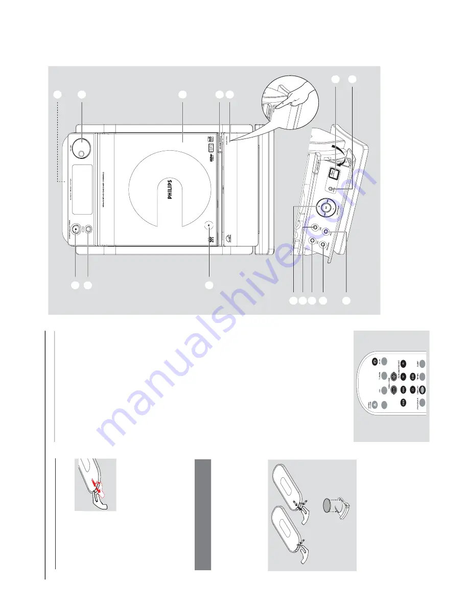
1-8
PREPARATIONS AND CONTROLS
Preparation
Setting the clock
After connecting MCM275 to the po
w
er suppl
y,
set the clock f
ir
st.
1
Press and hold
ST
ANDBY
-ON/ ECO
PO
WER
to switch the set to Standb
y mode
The display sho
ws the set time
-- --:-- -- flashes b
y default if y
ou ha
ve not set
the clock
2
In the standb
y mode
, press and hold
DISPLA
Y/
CLOCK
on the remote control
SET CLOCK
scrolls on the displa
y
24 HR
or
12 HR
appear
s f
or the initial
clock setting.
To
select 24-hour clock or
12-hour clock,
On the remote control,
press
V
OLUME +/-
once or more (or tur
n
V
OLUME
on the
set)
On the remote control,
press
DISPLA
Y/
CLOCK
to conf
ir
m
The hour
s digits star
t flashing
3
Hold do
wn or press
V
OLUME
+/-
repeatedl
y
to set the hour
s (or tur
n
V
OLUME
on the
set)
4
Press
DISPLA
Y/CLOCK
to conf
ir
m
The minutes digits star
t flashing
5
Hold do
wn or press
V
OLUME
+/-
repeatedl
y
to set the min
utes (or tur
n
V
OLUME
on the
set)
6
Press
DISPLA
Y/CLOCK
to confir
m
–
To exit without storing the clock setting press
ST
OP
9
Helpful hints:
–
The c
loc
k setting will be er
ased when the system
is disconnected fr
om the po
wer supply
.
–
The set will exit from the
cloc
k setting mode if
no button is pr
essed within 90 seconds
.
–T
o set the cloc
k automatically b
y using a time
signal whic
h is br
oadcast to
gether with the RDS
signal see c
hapter
RDS:
Automatic clock
setting via RDS
.
USB
/
Using the r
emote contr
ol
IMPOR
T
ANT!
–
Remo
ve the
pr
otective plastic tab
befor
e using the
re
mote control.
–
Alw
ays point the
re
mote control dir
ectly
to
w
ar
ds IR ar
ea.
Notes for r
emote control:
–
Fir
st select the source you wish to
contr
ol b
y pr
essing one of the source select
ke
ys on the r
emote contr
ol (for e
xample
CD
, TUNER).
–T
hen select the desired function (for
e
xample
ÉÅ
,
í
,
ë
).
To
r
eplace the r
emote contr
ols’
batter
y
CR
20
25
LIT
HI
UM
2
3
1
CA
UTION!
–
Remo
ve the battery if it is exhausted
or will not be used f
or a long time
.
–
Batteries contain chemical substances,
so the
y should be disposed of pr
operl
y.
1
Press and hold
1
as indicated.
2
Sim
ultaneousl
y, pull the batter
y tr
ay at
4
.
3
Remo
ve
the old batter
y and put a new CR2025
batter
y in place
.
4
Put back the batter
y tr
ay
.
1
2
3
!
9
@
0
#
7
6
5 4
8
%
$
All manuals and user guides at all-guides.com
Содержание MCM277/05
Страница 17: ...5 1 5 1 SET WIRING DIAGRAM All manuals and user guides at all guides com ...
Страница 23: ...LAYOUT DIAGRAM MAIN BOARD 5757 for 37 98 TOP SIDE 6 6 6 6 All manuals and user guides at all guides com ...
Страница 24: ...6 7 6 7 LAYOUT DIAGRAM MAIN BOARD 5757 for 37 98 BOTTOM SIDE All manuals and user guides at all guides com ...
Страница 25: ...CIRCUIT DIAGRAM MAIN BOARD 5757 for 37 98 6 8 6 8 All manuals and user guides at all guides com ...
Страница 27: ...LAYOUT DIAGRAM MAIN BOARD 5762 for 05 12 BOTTOM SIDE 6 10 6 10 All manuals and user guides at all guides com ...
Страница 28: ...CIRCUIT DIAGRAM MAIN BOARD 5762 for 05 12 6 11 6 11 All manuals and user guides at all guides com ...
Страница 32: ...7 2 7 2 LAYOUT DIAGRAM CD MCU BOARD TOP VIEW All manuals and user guides at all guides com ...
Страница 33: ...7 3 7 3 LAYOUT DIAGRAM CD MCU BOARD BOTTOM VIEW All manuals and user guides at all guides com ...
Страница 34: ...7 4 7 4 CIRCUIT DIAGRAM CD MCU BOARD CD PORTION All manuals and user guides at all guides com ...
Страница 35: ...7 5 7 5 CIRCUIT DIAGRAM CD MCU BOARD MCU PORTION All manuals and user guides at all guides com ...
Страница 39: ...CIRCUIT DIAGRAM AC POWER BOARD 8 3 8 3 All manuals and user guides at all guides com ...
Страница 50: ...SET BLOCK DIAGRAM 11 1 11 1 All manuals and user guides at all guides com ...
Страница 51: ...SET WIRING DIAGRAM 11 2 11 2 All manuals and user guides at all guides com a l l g u i d e s c o m ...
Страница 52: ...PCB LAYOUT MAIN BOARD TOP VIEW 12 1 12 1 All manuals and user guides at all guides com ...
Страница 53: ...12 2 12 2 PCB LAYOUT MAIN BOARD BOTTOM VIEW All manuals and user guides at all guides com ...
Страница 54: ...12 3 12 3 CIRCUIT DIAGRAM MAIN BOARD All manuals and user guides at all guides com ...
Страница 57: ...13 3 13 3 CIRCUIT DIAGRAM CD LIMIT SW BOARD ONLY FOR REFERENCE All manuals and user guides at all guides com ...
Страница 62: ...14 5 14 5 CIRCUIT DIAGRAM HP JACK SP ANT RC BOARD All manuals and user guides at all guides com ...
Страница 63: ...SET MECHANICAL EXPLODED VIEW 15 1 15 1 4 9 All manuals and user guides at all guides com ...


