2.6
Environmental Condition
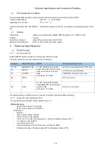
The environmental condition requirements and test method is according to UAN-D1590.
Ambient temperature
: max. 40 ° C - all climates
Apparatus acc. to spec.
: +5 to + 35 ° C
Vibration test (acc. IEC 60 068/2/6) : operational vibration test to be proceeded in operating position of the
set.
2.7
Quality
PQR-class: class 2 according to BLC A&MA PQR handbook V2.1 (2006-10-02)
Lifetime: 7 years
Tested According to: General Test Instruction UAN-D 1591
Measured According to: UAN_L 1059 unless otherwise stated
Technical Specification and Connection Facilities
3. Technical Specifications
3.1
Power Supply
3.1.1 Type
and
versions
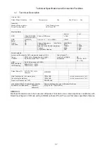
Build-inSMPS will be used for all models and stroke versions.
All using built in Power cord, will cater for all versions:
Versions
Region/Country SMPS
Detachable mains cords
12 / 05
EUROPE / UK
1) 100 ~240Vac nom. (wide
range from 90V~264Vac limit)
used in all versions except
India.
Frequency: 47~63Hz.
EU (/12) round 2-pin & UK (/05) 3-pin
37 NAFTA
UL flat pin (non-polarized)
n
i
p
-
2
d
n
u
o
r
d
e
i
f
i
t
r
e
c
O
R
T
E
M
N
I
M
A
T
A
L
5
5
n
i
p
-
2
d
n
u
o
r
U
E
C
A
P
A
8
9
94 India
2) 100 ~310Vac limit (India
compatible with up cost) used
only for India.
Frequency: 47~63Hz.
EU (/12) round 2-pin
All requirements per defined for each country should be met with sufficient testing.
3.1.2 Surge
Immunity
(Lightning
Test)
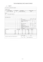
The product shall withstand mains interference’s of:
Differential mode:
2kV/2 ohm criteria C for Europe.
6kV/12 ohm criteria C for NAFTA.
Parameters:
Bi-wave
Open
circuit
voltage:
2/50us
Short
circuit
current:
8/20us
From +/1kV to +/-2kV (for Europe) or +/-6kV (for Nafta) in steps of 1kV.
10 shots per combination.
One shot per minute.
Serial impedance: 2 Ohm for Europe, 12Ohm for Nafta.
Polarity and phase: Positive (phase 90º) & Negative (phase 270º)
1-5
Содержание MCM2000/12
Страница 23: ...8 2 Fig D4 Cabinet Disassembly Instructions ...
Страница 30: ...Display Board Layout Diagram 12 3 12 3 ...
Страница 32: ...Power Board Layout Diagram 12 5 12 5 ...
Страница 36: ...Decoder Board Layout Diagram 12 9 12 9 ...
Страница 37: ...Exploded View DVDM PCB4 PCB3 Top cabinet PCB1 S105 S101 S107 S104 S106 S102 PCB2 Bottom chassis 13 1 13 1 ...
Страница 38: ...Revision List Revision List Version 1 0 Initial Release 14 1 ...

