3 - 1
CONNECTION AND CONTROLS
DB15 CONNECTOR
TO MAIN UNIT
SPEAKERS 4
AC MAINS
~
1
.0
00
IMPOR
T
ANT!
–
The type plate is located at the r
ear of
the system.
–
Bef
or
e connecting the
A
C
po
w
er cord
to the wall outlet,
ensur
e that all other
connections ha
v
e
been made
.
–N
ev
er mak
e or chang
e an
y
connections with the po
w
er switched on.
–
High v
oltage! Do not open.Y
ou run the
risk of getting an electric shock.
–
The machine does not contain an
y user-
ser
viceable par
ts
.
–
Modification of the pr
oduct could r
esult
in hazardous r
adiation of EMC or other
unsafe oper
ation.
To
a
void o
v
erheating of the system,
a
saf
ety cir
cuit has been built in.
Ther
ef
or
e
,
y
our system ma
y s
witch to Standb
y
mode automatically under e
xtr
eme
conditions.
If this ha
ppens,
let the system
cool do
wn bef
or
e r
eusing it
(not a
vailab
le
for all v
er
sions).
Speak
er
(right)
Speak
er
(left)
FM antenna
AC
p
o
w
er cor
d
Step 1:
Placing speak
ers and
subwoof
er
For best possib
le sur
round sound,
locate y
our
speak
er
s and subw
oofer as f
ollo
ws:
●
Place the left and r
ight speak
er
s at equal
distances from the
TV set and at an angle of
appro
ximatel
y 45 degrees from the listening
position.
●
Place the subwoof
er on the floor
.
Notes:
–T
o avoid magnetic interf
erence
, do not position
the fr
ont speak
er
s too c
lose to your
TV set.
–
Step 3:
Antenna connection
Connect the supplied FM antenna to the
respectiv
e ter
minal.
Adjust the position of the
antenna f
or optimal reception.
FM
Antenna
●
For better FM stereo reception, connect an
outdoor FM antenna to the FM
AERIAL (FM
ANTENNA) ter
minal.
Step 4:
Connecting
TV
IMPOR
T
ANT!
–Y
ou onl
y need to mak
e one video
connection fr
om the follo
wing options,
depending on the ca
pabilities of y
our
TV
system.
–
Connect the D
VD system dir
ectl
y to
the TV
.
Using
Video In jack (CVBS)
1
Use the composite video cab
le (y
ello
w) to
connect the system's
VIDEO
jack to the video
input jack (or labelled as
A/V In,
Video In,
Composite or Baseband) on the
TV set.
2
To
hear the sound of this D
VD Pla
yer through
your
TV
, use the audio cab
les (white/red-not
supplied) to connect
LINE OUT (L/R)
jacks of
the D
VD Pla
yer to the cor
responding
A
UDIO
IN jacks on the
TV
.
Step 2:
Connecting speak
ers
and subw
oofer
●
Connect the supplied DB15 cab
le to D
V
D
pla
yer’
s
DB15 CONNECT
OR
T
O
SPEAKER
jack and the Subw
oofer’
s
DB15
CONNECT
OR
T
O
MAIN UNIT
jack.
●
Connect the speak
er wires to the
SPEAKER
terminals on the subwoofer
, r
ight speak
er to "R"
and left speak
er to "L",
coloured (mar
ked) wire
to "+" and b
lack (unmar
ked) wire to "-".
Full
y
inser
t the stripped por
tion of the speak
er wire
into the ter
minal as sho
wn.
Notes:
–
Ensur
e that the speak
er cables ar
e corr
ectly
connected.
Impr
oper connections may damag
e the
system due to shor
t-circuit.
–F
or optimal sound perf
ormance
, use the
supplied speak
ers
.
–
Do not connect mor
e than one speak
er to any
one pair of +/- speak
er terminals
.
–
Do not connect speak
er
s with an impedance
lo
wer than the speak
er
s supplied.
Please r
ef
er to
the SPECIFIC
ATIONS section of this manual.
1
.0
00
DB15 CONNECTOR
TO MAIN UNIT
SPEAKERS 4
1
.0
00
Содержание MCD149
Страница 9: ...3 3 CONNECTION AND CONTROLS Controls Controls 7 1 2 3 4 5 6 8 9 0 1 7 8 6 4 0 7 8 5 2 3 9 2 ...
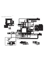
Страница 13: ...5 2 5 2 WIRING DIAGRAM ...
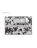
Страница 15: ...LAYOUT DIAGRAM DISPLAY BOARD 6 2 6 2 ...
Страница 16: ...7 1 7 1 CIRCUIT DIAGRAM MPEG BOARD ...
Страница 17: ...7 2 7 2 CIRCUIT DIAGRAM MPEG BOARD ...
Страница 18: ...LAYOUT DIAGRAM MPEG BOARD 7 3 7 3 ...
Страница 19: ...8 1 8 1 SCART BOARD ...
Страница 20: ...USB BOARD USB BOARD 9 1 9 1 ...
Страница 21: ...18 17 14 16 15 22 15 13 19 20 27 24 21 28 12 25 26 EXPLODE DIAGRAM 10 1 10 1 ...


