


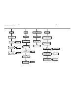


Disassembly Diagram
3-1
3-1
B.Remove the Top-cabinet
B1.Loose 2pcs screws(3 x 6 KB) of both side
near to the back side.
B2.Loose 2pcs screws(3 x 8 Km) of both side
near to the front cabinet.
B3.Loose 1pc screw(3 x10 FA) of the back side.
C. Loose 1pc screw(3 x 8 BA) to remove
the Power Board
E.Remove Decoder Board
E1.Loose 2pcs screws(3 x 10 FA) of the back side.
E2.Loose 2pcs screws(3 x 8 BA) of the decoder board.
D.Loose 4pcs screws(3 x 10 PWA)
to remove DVD Loader Driver
F.Loose 2pcs screws(3 x 8 FT)
to remove the Front Cabinet
G.Loose 1pc screw(3 x 8 BA)
to remove the Headphone Board
A.Open the DVD Door and loose 2 clipps
to remove the door
H. Loose 6pcs screws(2 x 8 PA) to remove
the Display Board
A
B1
B2
B3
C
D
E1
E2
F
G
H
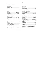
Содержание MCD110
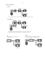
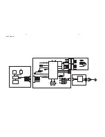
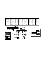
Страница 14: ...4 2 4 2 Wiring Diagram Display Board DVD Mechanism Driver Power Board Decoder Board USB Board ...
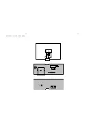
Страница 17: ...6 2 6 2 LED Display Board Layout Diagram ...
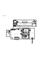
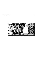
Страница 19: ...Power Board Layout Diagram 7 3 7 3 ...
Страница 26: ...8 7 8 7 Decoder Board ...
Страница 27: ...9 1 9 1 Exploded View ...


