5-1
5-1
DISASSEMBLY
DIAGRAM
A
C
BOTTOM
CAB
.
1
)
Remove
2
screws
A
as
indicated
.
2
)
Remove
3
screws
B
as
indicated
.
2
)
Remoce
6
screws
C
as
indicated
to
loosen
the
Bottom
Cabinet
.
Dismantling
of
the
Bottom
Cabinet
Dismantling
of
the
Front
Cabinet
and
PCB
Board
.
D
1
)
Remove
2
screws
D
as
indicated
to
loosen
the
Front
Cabinet
.
2
)
Remove
9
screws
E
as
indicated
to
loosen
the
Front
Board
.
3
)
Remove
2
screws
F
as
indicated
to
loosen
the
Main
Board
.
E
B
F
Содержание MCD107
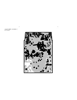
Страница 12: ...6 3 6 3L LAYOUT DIAGRAM MAIN BOARD TOP SIDE ...
Страница 13: ...6 4 6 4 LAYOUT DIAGRAM MAIN BOARD BOTTOM SIDE ...
Страница 19: ...7 6 7 6 LAYOUT DIAGRAM DVD BOARD ...
Страница 21: ...8 2 8 2 LAYOUT DIAGRAM FRONT BOARD TOP SIDE ...
Страница 22: ...8 3 8 3 LAYOUT DIAGRAM FRONT BOARD BOTTOM SIDE ...
Страница 23: ...SET EXPLODED VIEW DIAGRAM 9 1 9 1 ...

