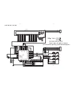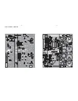
3 - 3
CONNECTION AND CONTROLS
Step 5:
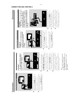
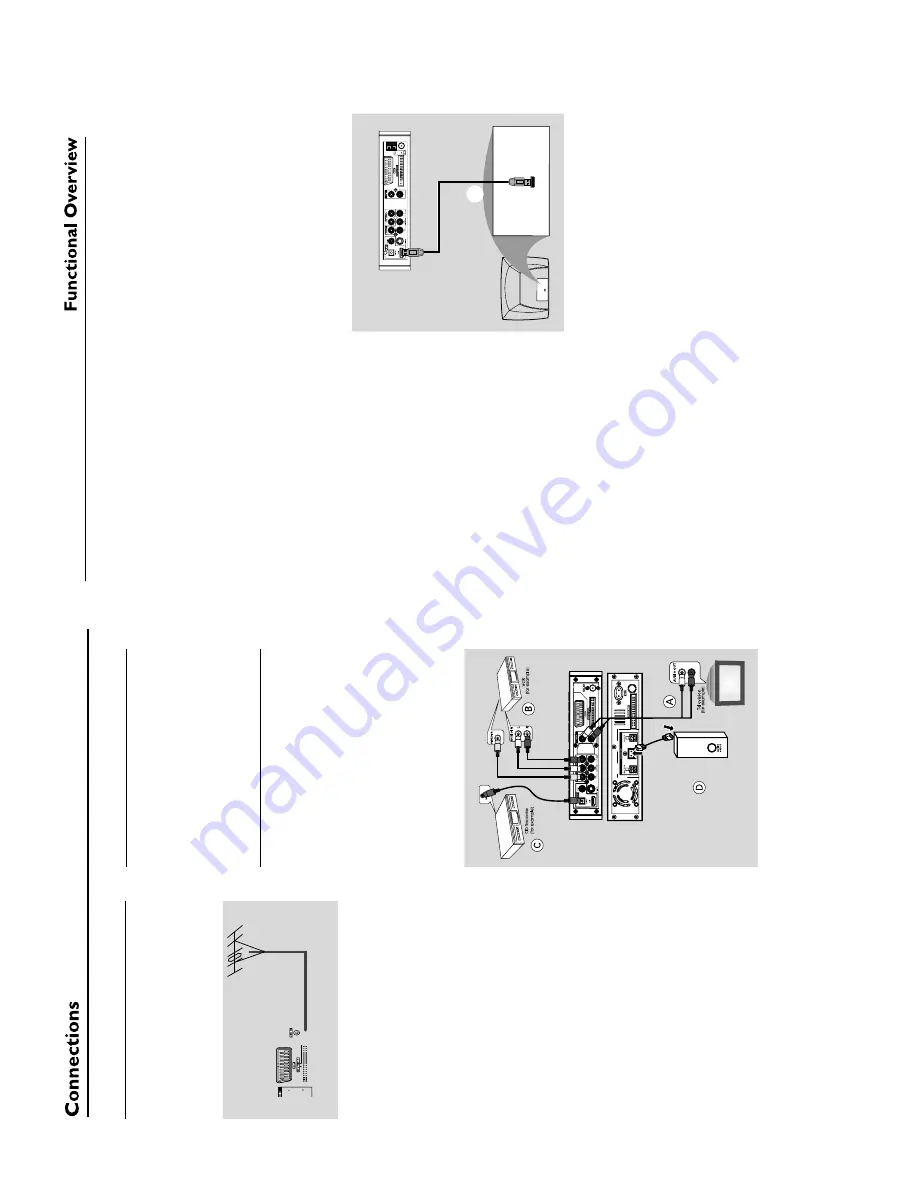
Connecting FM antenna
1
Connect the supplied FM antenna to the FM (75
Ω
) jack.
Extend the FM antenna and f
ix its end to
the wall.
For better FM stereo reception, connect an
external FM antenna (not supplied).
Note:
–
Adjust the position of the antennas f
or optimal
reception.
–P
osition the antennas as f
ar as possible fr
om
your
TV
, VCR or other r
adiation source to pr
event
unw
anted interf
erence
.
Step 6:
Connecting the po
w
e
r
cor
d
After e
v
er
ything is connected pr
operl
y,
plug in the
A
C
po
w
er cord to the po
w
e
r
outlet.
Never mak
e or change an
y connection with the
po
w
er switched on.
Ad
ditional:
Connecting
ad
ditional equipment
IMPOR
T
ANT!
–
Some discs are cop
y-pr
otected.
Y
o
u
cannot r
ecor
d the disc thr
ough a
VCR or
digital r
ecor
ding de
vice
.
–W
hen making connections,
mak
e
sur
e
the colour of cab
les matches the colour
of jacks.
–A
lwa
ys r
e
fer to the o
wner’
s man
ual of
the other equipment f
or complete
connection and usa
g
e
details.
Vie
wing and listening to the pla
yback of
other equipment
A
●
Connect the system's
A
UX IN L/R
jacks to the
A
UDIO OUT jacks on the other audio/visual
device (such as a
TV
, VCR,
Laser Disc pla
yer or
cassette deck).
Bef
ore star
ting oper
ation,
press
SOURCE
on
the front panel to select
A
UX or press
AUX
on
the remote in order to activate the input source
.
Using the
VCR f
or r
ecor
ding D
VDs
B
●
Connect one of the system's
VIDEO
jack to the
cor
responding
VIDEO IN jack and
AUDIO
OUT L/R
jacks to the
A
UDIO IN jacks on the
VCR.
This will allo
w y
ou to mak
e analogue stereo
(tw
o channel,
r
ight and left) recordings.
Recor
ding (digital)
C
●
Connect the system's
CO
AXIAL
or
OPTICAL
jack to the DIGIT
AL IN jack on a
digital recording device
.
Bef
ore star
ting oper
ation,
set the DIGIT
AL OUT
according to the audio connection. (See
"DIGIT
AL OUT".)
Connecting an activ
e subw
oof
er
D
●
Connect the D
VD micro system's
SUBW
OOFER
jack to the
A
UDIO INPUT
jack on an activ
e subwoof
er (not supplied).
Connecting to a
TV with HDMI Jack
E
HDMI connects untouched and uncompressed
digital tr
ansmission for the highest and cr
ispest
sound/image quality
.
It has plug and pla
y capability using onl
y one
cab
le f
or both audio/video output.
●
Use a HDMI cab
le (not supplied) to connect the
HDMI
jack on the D
VD Pla
yer to
HDMI IN
on a HDMI compatib
le device (e
.g.;
TV
, Projector
,
Adaptor).
➜
It ma
y tak
e a while f
or the D
VD pla
yer and
input device to comm
unicate and initialise
.
➜
Pla
yback star
ts automaticall
y.
HDMI IN
HDMI IN
HDTV
E
Notes:
–P
roceed to "Setup Menu Options"
➜
"VIDEO
SETUP P
A
GE"
➜
"HDMI SETUP" f
or detailed
HDMI setup.
–
If you ar
e using the HDMI as audio source
mak
e sur
e that "DIGIT
AL OUTPUT" is set to "PCM
only" (see "Setup Menu Options"
➜
"A
UDIO
SETUP P
A
GE"
➜
"DIGIT
AL A
UDIO
SETUP
").
–T
o stop sound output fr
om your
TV after
making the HDMI connection,
mak
e sur
e that
"DIGIT
AL OUTPUT" is set to "SPDIF OFF" (see
"Setup Menu Options"
➜
"A
UDIO SETUP P
A
GE"
➜
"DIGIT
AL A
UDIO
SETUP
").
Содержание MCD 728
Страница 2: ...1 1 HANDLING CHIP COMPONENTS ...
Страница 3: ...1 2 ...
Страница 5: ...2 2 ...
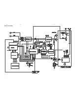
Страница 14: ...5 2 5 2 SET BLOCK DIAGRAM ...
Страница 17: ...6 2 6 2 LAYOUT DIAGRAM VFD BOARD ...
Страница 19: ...7 2 7 2 LAYOUT DIAGRAM TUNER BOARD ...
Страница 21: ...8 2 8 2 LAYOUT DIAGRAM AMP BOARD ...
Страница 23: ...9 2 9 2 LAYOUT DIAGRAM CPU BOARD ...
Страница 25: ...10 2 10 2 LAYOUT DIAGRAM Pre AMP BOARD ...
Страница 31: ...13 6 13 6 LAYOUT DIAGRAM DVD MPEG BOARD MPEG board is not repaired program for referrence only ...


