


3 - 2
Step 5:
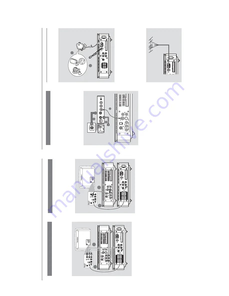
Connecting FM/MW
antennas
SUB WOOFER
1
2
FM
antenna
MW
antenna
fix the cla
w into
the slot
Connect the supplied MW loop antenna to the
MW jack. Place the MW loop antenna on a shelf
or attach to a stand or wall.
Connect the supplied FM antenna to the FM (75
ohm
) jack.
Extend the FM antenna and f
ix its end
the wall.
For better FM stereo reception, connect an
external FM antenna (not supplied).
Note:
–
Adjust the position of the antennas f
or optimal
reception.
–P
osition the antennas as f
ar as possible fr
om
your
TV
, VCR or other r
adiation source to pr
event
unw
anted interf
er
ence
.
Connections
Using an accessor
y RF modulator
IMPOR
T
ANT!
–
If y
our
TV onl
y has a single
Antenna In
jack (labeled as 75 ohm or RF In),
y
ou
will need an RF modulator in or
der to
vie
w D
VD pla
yback on the
TV
. See y
our
electr
onics r
etailer or contact Philips f
or
details on RF modulator a
vailability and
operations.
LINE OUT
3
2
AUDIO IN
R L
VIDEO
IN
TO TV
INT IN
CH3 CH4
ANT IN
RF coaxial cable to
TV
1
Use the composite video cab
le (y
ello
w) to
connect the D
VD system’
s
VIDEO OUT jack to
the video input jack on the RF modulator
.
Use an RF coaxial cab
le (not supplied) to
connect
ANTENNA OUT or
T
O
TV jack on the
RF modulator to the
Antenna IN jack on the
TV
.
Connect the
Antenna or Cab
le
TV ser
vice signal
to the
ANTENNA IN or RF IN jack on the RF
modulator
. (It ma
y ha
ve been connected to your
TV previousl
y. Disconnect it from the
TV
.)
1
2
1
2
3
to
CONNECTION AND CONTROLS
Using S-Video jack
IMPOR
T
ANT!
–
If S-Video is used for D
VD pla
yback
connection,
the system’
s
VIDEO OUT
setting will need to be chang
ed
accor
dingly
.
SUB WOOFER
LINE OUT
1
2
1
Use an S-Video cab
le (not supplied) to connect
the D
VD system’
s S-VIDEO jack to the S-Video
input jack (or labeled as
Y/C or S-VHS) on the
TV
.
2
To
hear the
TV channels through this D
VD
system,
use the audio cab
les (white/red) to
connect
A
UDIO IN-TV jacks to the
cor
responding
A
UDIO OUT jacks on the
TV
.
Connections
Using Component
Video jacks (Y Pb Pr)
IMPOR
T
ANT!
–
The pr
o
gressiv
e scan video quality is
onl
y possib
le when using
Y Pb Pr
, and a
pr
o
gressiv
e scan
TV is r
equir
ed.
SUB WOOFER
LINE OUT
1
2
1
Use component video cab
les (red/b
lue/green -
not supplied) to connect the D
VD system's
Y Pb
Pr jacks to the cor
responding Component video
input jacks (or labeled as
Y Pb/Cb Pr/Cr or
YUV)
on the
TV
.
2
To
hear the
TV channels through this D
VD
system,
use the audio cab
les (white/red) to
connect
A
UDIO IN-TV jacks to the
corresponding
A
UDIO OUT jacks on the
TV
.
3
If y
ou are using a Progressiv
e Scan
TV (TV must
indicate Progressiv
e Scan or ProScan capability),
to activate
TV Progressiv
e Scan,
please refer to
your
TV user man
ual.
For D
VD system
Progressiv
e Scan function,
see
“Getting Star
ted-
Setting up Progressiv
e Scan f
eature”.
Note:
–
If your
TV does not suppor
t Pr
ogr
essive Scan,
you
will not be able to vie
w the pictur
e
.
Pr
ess
SYSTEM
on the r
emote to exit the system
menu and then
DISC
to exit
p
ro
gr
essive scan.
Содержание MCD 709
Страница 2: ...1 1 HANDLING CHIP COMPONENTS ...
Страница 3: ...1 2 ...
Страница 5: ...2 2 ...
Страница 14: ...5 1 5 1 4 SOFTWARE VERSION CHECK AND UPGRADING ...
Страница 15: ...5 2 5 2 SET BLOCK DIAGRAM ...
Страница 16: ...5 3 5 3 SET WIRING DIAGRAM ...
Страница 18: ...6 2 6 2 LAYOUT DIAGRAM VFD BOARD ...
Страница 20: ...7 2 7 2 LAYOUT DIAGRAM ECO6 02 TUNER BOARD not for 37 ...
Страница 22: ...7 4 7 4 LAYOUT DIAGRAM ECO6 01 TUNER BOARD only for 37 ...
Страница 24: ...8 2 8 2 LAYOUT DIAGRAM AMP BOARD ...
Страница 26: ...9 2 9 2 LAYOUT DIAGRAM CPU BOARD ...
Страница 28: ...10 2 10 2 LAYOUT DIAGRAM ALC VOLUME BOARD ...
Страница 34: ...11 6 11 6 LAYOUT DIAGRAM DVD MPEG BOARD MPEG board is not repaired program for referrence only ...


