background image

1-8

PREPARATIONS AND CONTROLS

Pr

eparations

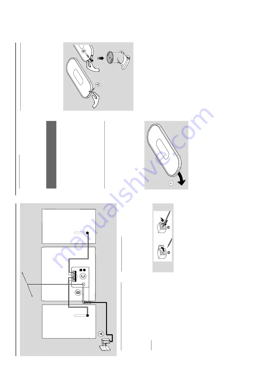
Rear connections

The type plate is located at the r

ear of the

system.

For user

s in the U.K.:

 please follo

w the

instructions .

A

Po

w

er

Bef

ore connecting the 

AC

 po

w

er cord to the

wall outlet, ensure that all other connections

ha

ve

 been made

.

W

arning!

–F

or optimal performance

, use only the

original po

wer cable

.

Nev

er mak

e or change an

y connections

with the po

wer s

w

itched on.

To

 av

oid o

verheating of the system,

 a safety

circuit has been built in.

  Ther

efor

e

, your

system may s

witch to Standb

y mode

automatically under e

xtr

eme conditions

. If

this happens

, let the system cool do

wn

befor

e r

eusing it 

(not available f

or all ver

sions).

T-sha

pe Antenna

Speak

er

(left)

Speak

er

(right)

AC

 po

w

er cor

d

B

Speak

ers Connection

Fr

ont Speak

ers

Connect the speak

er wires to the Speak

er

ter

minals,

 r

ight speak

er to "

R

" and left speaker to

"

L

", colored (mar

ked) wire to "

+

" and b

lack

(unmar

ked) wire to "

-

".

Full

y inser

t the str

ipped por

tion of the speak

er

wire into the terminal as sho

wn.

Notes:

–F

or optimal sound perf

ormance

, use the

supplied speak

ers

.

Do not connect mor

e than one speak

er to any

one pair of +/- speak

er terminals

.

Do not connect speak

er

s with an impedance

lo

wer than the speak

er

s supplied.

  Please ref

er to

the SPECIFIC

ATIONS section of this manual.

plastic

pr

otectiv

e

sheet

C

Optional connection

The optional equipment and connecting cords

are not supplied.

  Ref

er to the oper

ating

instr

uctions of the connected equipment f

or

details.

Connecting other equipment to y

our

system

Connect the audio left and r

ight OUT ter

minals

of a 

TV

, VCR,

 Laser Disc pla

ye

r, D

VD pla

yer or

CD Recorder to the 

A

UX 

ter

minals.

Note:

If you ar

e connecting equipment with a mono

output (a single audio out terminal), connect it to

the 

A

UX left terminal.


Alternatively

, you can use a

“single to double”

 cinc

h cable (the output sound

still r

emain mono).

Bef

or

e using the r

emote contr

ol

1

Pull out the plastic protective sheet.

2

Select the source y

ou wish to control b

y

pressing one of the source select k

eys on the

remote control (f

or example CD

, TUNER).

3

Then select the desired function (for example

  2  ;

 ,   

S

 , 

T

).


Replacing batter

y (lithium

CR2025) into the r

emote contr

ol

1

Pull out the knob 

A

 slightl

y to the left.

2

Pull out the batter

y compar

tment 

B

 .

3

Replace a new batter

y and full

y inser

t the

batter

y compar

tment back to the or

iginal

position.


CA

UTION!

Batteries contain chemical substances

, s

o

the

y should be disposed of properly

.

Pr

eparations

Содержание MCB240/22

Страница 1: ...ct to modification GB 3141 785 30511 Micro System TABLE OF CONTENTS Page Location of PC Boards Versions Variation 1 2 Specifications 1 3 Measurement Setup 1 4 Service Aids Safety Instruction etc 1 5 to 1 6 Lead free Information Service Instruction 1 7 Preparations Controls Troubleshooting 1 8 to 1 10 Disassembly Instructions Service positions 2 Service Test Program 3 1 Set Block Diagram 4 1 Set Wi...

Страница 2: ...ital in Matrix Surround RDS x x News x x Dolby Pro Logic DPL Incredible Surround Karaoke Features Voltage Selector ECO Power Standby LCD Display Off x x ECO6 Tuner Board Systems Non Cenelec ECO6 Tuner Board Systems Cenelec DAB Dual Band VERSION VARIATIONS Type Versions MCB240 Features Board in used 22 DAB Single Band x x ...

Страница 3: ...v 40kHz 18dB AMPLIFIER Output power L R 2 x 4 8W 4Ω 1kHz 10 THD Frequency response within 3dB 60Hz 16kHz Digital Sound Control DSC Jazz Rock Pop Classic Dynamic Bass Boost DBB ON OFF COMPACT DISC Frequency response within 3dB 80Hz 12kHz Output level in Vrms 500mV Zout 100Ω Signal Noise ratio A weighted 57dBA Crosstalk at 1kHz 26dB Channel difference at 1kHz 2dB Emphasis 15 50 µS switched automatic...

Страница 4: ...7122 707 89001 Tuner AM MW LW To avoid atmospheric interference all AM measurements have to be carried out in a Faraday s cage Use a bandpass filter or at least a high pass filter with 250Hz to eliminate hum 50Hz 100Hz RF Generator e g PM5326 Ri 50 Bandpass 250Hz 15kHz e g 7122 707 48001 LF Voltmeter e g PM2534 DUT RF Generator e g PM5326 S N and distortion meter e g Sound Technology ST1700B Use a...

Страница 5: ...822 397 30155 SBC429 Audio Signals disc 4822 397 30184 Dolby Pro logic Test Disc 4822 395 10216 ESD Equipment Anti static table mat large 1200x650x1 25mm 4822 466 10953 Anti static table mat small 600x650x1 25mm 4822 466 10958 Anti static wristband 4822 395 10223 Connector box 1MΩ 4822 320 11307 Extension cable to connect wristband to conn box 4822 320 11305 Connecting cable to connect table mat t...

Страница 6: ...ectrostatische ontladingen ESD Onzorgvuldig behandelen tijdens reparatie kan de levensduur drastisch doen verminderen Zorg ervoor dat u tijdens reparatie via een polsband met weerstand verbonden bent met hetzelfde potentiaal als de massa van het apparaat Houd componenten en hulpmiddelen ook op ditzelfde potentiaal I AVVERTIMENTO Tutti IC e parecchi semi conduttori sono sensibili alle scariche stat...

Страница 7: ...es has to be purchased at external companies Special information for BGA ICs always use the 12nc recognizable soldering temperature profile of the specific BGA for de soldering always use the lead free temperature profile in case of doubt lead free BGA ICs will be delivered in so called dry packaging sealed pack including a silica gel pack to protect the IC against moisture After opening dependent...

Страница 8: ...peaker terminals Do not connect speakers with an impedance lower than the speakers supplied Please refer to the SPECIFICATIONS section of this manual plastic protective sheet C Optional connection The optional equipment and connecting cords are not supplied Refer to the operating instructions of the connected equipment for details Connecting other equipment to your system Connect the audio left an...

Страница 9: ...eset radio station up down for MP3 CD on the remote only skips to the beginning of a current previous subsequent album TUNE 1 2 S T for DAB scrolls an option list for TUNER tunes to radio stations down up for CD MP3 CD on the remote only fast searches back and forward within a track disc press and hold skips to the beginning of a current previous subsequent track ENTER press to select an option DA...

Страница 10: ...tion REPEAT repeats a track album disc program entire disc SHUFFLE plays disc tracks in random order n connects headphones Notes for remote control First select the source you wish to control by pressing one of the source select keys on the remote control for example CD TUNER Then select the desired function for example 2 S T 1 10 ...

Страница 11: ...directly toward IR sensor on the front of the system Set the clock correctly Press TIMER to switch on the timer Power has been interrupted or the power cord has been disconnected Reset the clock timer Problème Solution Important notes for users in the U K Mains plug This apparatus is fitted with an approved 13 Amp plug To change a fuse in this type of plug proceed as follows 1 Remove fuse cover an...

Страница 12: ...screws H as indicated to loosen the Gear Motor Module 4 Loosen 4 screws I see Figure 4 to remove the Key_C Board 5 Loosen 2 screws J see Figure 4 to remove the Display Board Figure 3 Dismantling of the Front Boards and CD Door 6 Loosen 4 screws K see Figure 3 to remove the Power Key Board 7 Board 8 Lever Bracket Right Left then remove CD door Repair Hints Service Positions Note The flex cables are...

Страница 13: ...d The model number and software version now can be shown on the display e g MCB240 for 3 sec then goto version no XXX III Display Segment Test STEP 1 After plug in power within 5 sec on the front panel press PRESET DOWN key first do not release STEP 2 Then press PROGRAM key on the panel two keys are pressed All the LCD display segment will be turned on IV Tuner Alignment Set Test STEP 1 After plug...

Страница 14: ...4 1 4 1 SET BLOCK DIAGRAM ...

Страница 15: ...5 1 5 1 SET WIRING DIAGRAM ...

Страница 16: ...6 1 6 1 Printed Circuit Board Side A POWER BOARD Printed Circuit Board Side A ...

Страница 17: ...6 2 6 2 CIRCUIT DIAGRAM ...

Страница 18: ...nted to be repaired on component level Circuit Diagram and Printed Circuit Board drawings are published for orientation only In case of defects please replace the entire board The board can be ordered with codenumber 9940 000 02999 for 22 25 ...

Страница 19: ...LAYOUT DIAGRAM MAIN BOARD TOP SIDE 7 2 7 2 ...

Страница 20: ...7 3 7 3 LAYOUT DIAGRAM MAIN BOARD BOTTOM SIDE ...

Страница 21: ...CIRCUIT DIAGRAM MAIN BOARD PART 1 7 4 7 4 ...

Страница 22: ...CIRCUIT DIAGRAM MAIN BOARD PART 2 7 5 7 5 ...

Страница 23: ...CIRCUIT DIAGRAM MAIN BOARD PART 3 7 6 7 6 ...

Страница 24: ...CIRCUIT DIAGRAM MAIN BOARD PART 4 7 7 7 7 ...

Страница 25: ...CIRCUIT DIAGRAM MAIN BOARD PART 5 7 8 7 8 ...

Страница 26: ...CIRCUIT DIAGRAM MAIN BOARD PART 6 7 9 7 9 ...

Страница 27: ...CIRCUIT DIAGRAM MAIN BOARD PART 7 7 10 7 10 ...

Страница 28: ...CIRCUIT DIAGRAM MAIN BOARD PART 8 7 11 7 11 ...

Страница 29: ...LAYOUT DIAGRAM HEADPHONE BOARD LAYOUT DIAGRAM DOOR SWITCH BOARD 7 12 7 12 CIRCUIT DIAGRAM HEADPHONE BOARD CIRCUIT DIAGRAM DOOR SWITCH BOARD ...

Страница 30: ...ntation only In case of defects please replace the entire board The board can be ordered with codenumber 9940 000 03001 for 22 9940 000 03064 for 25 8 1 8 1 DAB ADAPTOR BOARD LAYOUT DIAGRAM POWER KEY BOARD TOP SIDE LAYOUT DIAGRAM POWER KEY BOARD BOTTOM SIDE LAYOUT DIAGRAM VOLUME BOARD TOP SIDE LAYOUT DIAGRAM VOLUME BOARD BOTTOM SIDE ...

Страница 31: ...LAYOUT DIAGRAM DAB ADAPTOR BOARD TOP SIDE LAYOUT DIAGRAM DAB ADAPTOR BOARD BOTTOM SIDE 8 2 8 2 ...

Страница 32: ...8 3 8 3 CIRCUIT DIAGRAM DAB ADAPTOR BOARD PART 1 ...

Страница 33: ...CIRCUIT DIAGRAM DAB ADAPTOR BOARD PART 2 CIRCUIT DIAGRAM POWER KEY BOARD CIRCUIT DIAGRAM VOLUME KEY BOARD 8 4 8 4 ...

Страница 34: ...rd drawings are published for orientation only In case of defects please replace the entire board The board can be ordered with codenumber 9940 000 03007 9 1 9 1 LCD BRACKET BOARD LAYOUT DIAGRAM LCD BRACKET BOARD TOP SIDE LAYOUT DIAGRAM LCD BRACKET BOARD BOTTOM SIDE CIRCUIT DIAGRAM LCD BRACKET BOARD ...

Страница 35: ...10 1 10 1 NAVIGATION KEY BOARD SPEAKER JACK BOARD LAYOUT DIAGRAM NAVIGATION KEY BOARD TOP SIDE LAYOUT DIAGRAM NAVIGATION KEY BOARD BOTTOM SIDE LAYOUT DIAGRAM SPEAKER JACK BOARD TOP SIDE ...

Страница 36: ...CIRCUIT DIAGRAM NAVIGATION KEY BOARD 10 2 10 2 CIRCUIT DIAGRAM SPEAKER JACK BOARD ...

Страница 37: ... 2 3 4 5 6 7 8 9 11 12 13 14 15 16 17 18 19 21 22 23 24 25 26 27 28 29 31 33 37 36 35 38 39 32 41 34 42 43 44 45 46 47 48 49 60 61 62 63 64 65 67 68 71 72 73 74 75 76 60 61 62 63 64 65 66 72 67 68 69 71 73 74 75 76 69 66 SCREW LIST ...

Страница 38: ...FOOT L24 5XW6XH1 5 25 9940 000 03015 RUBBER PAD DIA6MMX1 5 27 9965 000 16216 CD DAMPER YELLOW 30DEG 28 9940 000 03057 CD MECHANISM DA23ZPH 29 9965 000 16217 CD DAMPER WHITE 40DEG 31 9940 000 03046 BRACKET FUNCTION KEY 32 9940 000 03025 CAP FUNCTION KEY 33 9940 000 03042 BRACKET PLAY STOP 34 9940 000 03026 CAP PLAY KEY 35 9940 000 03027 CAP STOP KEY 36 9940 000 03043 BRACKET SEARCH ALBUM 37 9940 00...

Страница 39: ...REVISION LIST 12 1 1 0 Manual 3141 785 30510 Initial Service Manual released 1 1 Manual 3141 785 30511 In this version Page 11 2 Electrical Parts List of DAB Adaptor Board Ass y added ...

Отзывы: