


I
NSTALLATION
D
ESIGNER
S
UITE
T
OUCH
S
CREEN
U
SER
’
S
G
UIDE
4
Installation
The Designer Suite Touch Screen is available in two mounting configurations: wall-mount, surface or
flush (LDTS07) and rack-mount (LDTS07RM). Refer to appropriate installation method below.
The Lytemode ILS Network consists of a single CAT5e cable connecting all ILS devices in a daisy
chain manner. All units connect to the network using a 9-pin connector (included).
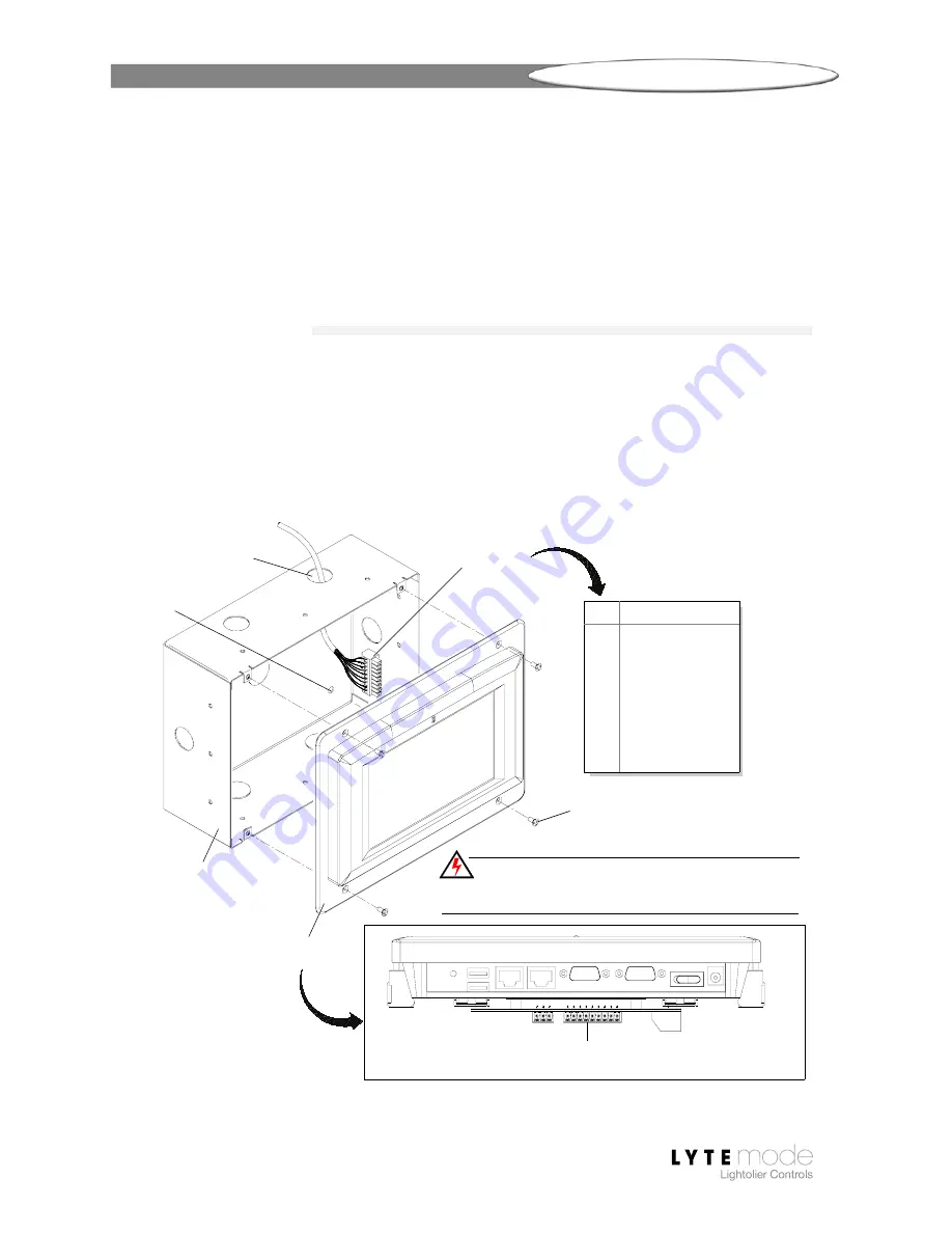
LDTS07 (Wall-Mount)
To install wall-mount unit:
Step 1. Unpack LDTS07 Touch Screen and inspect for any signs of shipping damage.
Step 2. Route ILS network cable through appropriate knock-out hole and install rough-in
box (sold separately) into wall (
Figure 1
).
Step 3. Connect ILS network cable to Touch Screen ILS connector.
Step 4. Install Touch Screen onto rough-in box using four #6 flat head screws.
Figure 1: Installing LDTS07 Wall-Mount Touch Screen
Rough-In Box
Knock-Out Hole
Touch Screen Assembly
(Wall-Mount Version)
ILS 9-Pin
Connector
From ILS Network
(Part # ILSCLBTSII,
TOP VIEW
ILS Network
1
WH/OR (+ Data)
2
OR (- Data)
3
SHIELD
4
WH/GN (+ Volts)
5
GN (Ground)
6
WH/BL (+ Volts)
7
BL (Ground)
8
WH/BR (+ Volts)
9
BR (Ground)
PIN SIGNAL
WARNING!
Remove power from house service before connecting
any wiring or cables to the Designer Suite Touch Screen.
#6 Flat Head Screw (4)
All other connectors are not
applicable to this installation
Connection
Surface
Mounting
Hole (4)
Sold Separately)