Mechanical Instructions
4.
4.3.4
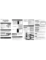
IR & LED Board
Refer to next figure for details.
1.
Unplug connectors [1].
2.
Use a flat screw driver to release the clip by pushing it in
the indicated direction [2].
3.
Lift the board and take it out of the set.
When defective, replace the whole unit.
Figure 4-6 IR & LED Board
4.3.5
Key Board
Refer to next figure for details.
1.
Unplug connectors.
2.
Remove the screws [1].
3.
Lift the unit and take it out of the set.
When defective, replace the whole unit.
Figure 4-7 Key Board
4.3.6
Display Supply Panel
Refer to next figure for details (is for 42” set, for other
screensizes the process might slightly deviate):
1.
Unplug connectors [1].
2.
Remove the fixation screws [2].
3.
Take the board out.
Figure 4-8 Display Supply Panel (42” set)
4.3.7
iBoard
Refer to next figure for details.
1.
Unplug connectors.
2.
Remove the screws [1].
3.
Lift the unit and take it out of the set.
When defective, replace the whole unit.
Figure 4-9 iBoard
H_17650_09
8
.ep
s
1
8
010
8
2
1
H_17650_094.ep
s
1
8
010
8
1
H_17740_021.ep
s
2
3
010
8
1
1
2
2
2
2
2
2
2
2
1
1
1
8
510_209_090409.ep
s
090409
1


