


Mechanical Instructions
EN 15
LC7.2E LA
4.
4.3.9
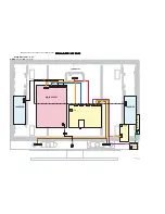
LCD Panel
The disassembly method for the LCD panel differs per model
or screen size. The following description applies to the 32”
model, but for the other screen sizes, the method is similar.
1.
Refer to next figure(s).
2.
Unplug the connectors on the Main Supply Panel [a] and
the LED & IR board [c].
3.
Unplug the connectors [d] from the loudspeakers.
4.
Do NOT forget
to unplug the LVDS connector [e] from the
SSB.
Important:
Be careful, as this is a fragile connector!
5.
Remove T10 parker screw [b] that holds the Side I/O
module bracket.
6.
Remove T10 parker screws [f] of the central sub-frame.
7.
Remove LCD panel fixation screws [g] and lift the complete
central sub-frame from the set (incl. the PSU, SSB, and
Side I/O boards and wiring).
8.
Lift the LCD panel [7] from the front cabinet.
Figure 4-21 LCD panel 32” [1/2]
Figure 4-22 LCD panel 32” [2/2]
4.4
Set Re-assembly
To re-assemble the whole set, execute all processes in reverse
order.
Notes:
•
While re-assembling, make sure that all cables are placed
and connected in their original position. See figure "Cable
dressing".
•
Pay special attention not to damage the EMC foams.
Ensure that EMC foams are mounted correctly (one is
located above the LVDS connector on the display, between
the LCD display and the metal sub-frame).
d
d
a
e
G_16860_067.eps
310107
c (1x)
g (2x)
f (3x)
f (2x)
f (1x)
g (2x)
b
G_16850_015.eps
110107
7