Alignments
8.
4.
Select AGC with the UP/DOWN cursor keys.
5.
Adjust the AGC-value (default value is 28) with the LEFT/
RIGHT cursor keys until the voltage at pin 1 of the tuner lies
between 3.8 and 2.3 V.
6.
Select AFW with the UP/DOWN cursor keys and set to
OFF.
7.
Switch the set to STANDBY.
YD (Y-delay)
Always set to 8.
CL (cathode drive level)
Always set to 7.
AFA
Read only bit, for monitoring purpose only.
AFB
Read only bit, for monitoring purpose only.
8.3.3
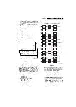
White Tone
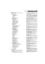
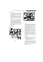
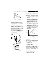
Figure 8-8
In the WHITE TONE sub menu, the values of the black cut off
level can be adjusted. Normally, no alignment is needed for the
WHITE TONE. You can use the given default values.
The colour temperature mode (NORMAL, COOL and WARM)
and the colour (R, G, and B) can be selected with the UP/
DOWN RIGHT/LEFT cursor keys. The value can be changed
with the LEFT/RIGHT cursor keys. First, select the values for
the NORMAL colour temperature. Then select the values for
the COOL and WARM mode. After alignment, switch the set to
standby, in order to store the alignments.
Default settings:
1.
NORMAL
(colour temperature = 11500 K):
–
NORMAL R = 32
–
NORMAL G = 35
–
NORMAL B = 30
2.
COOL
(colour temperature = 14000 K):
–
DELTA COOL R = 0
–
DELTA COOL G = -5
–
DELTA COOL B = 5
3.
WARM
(colour temperature = 8200 K):
–
DELTA WARM R = 8
–
DELTA WARM G = -3
–
DELTA WARM B = 2
8.3.4
Geometry
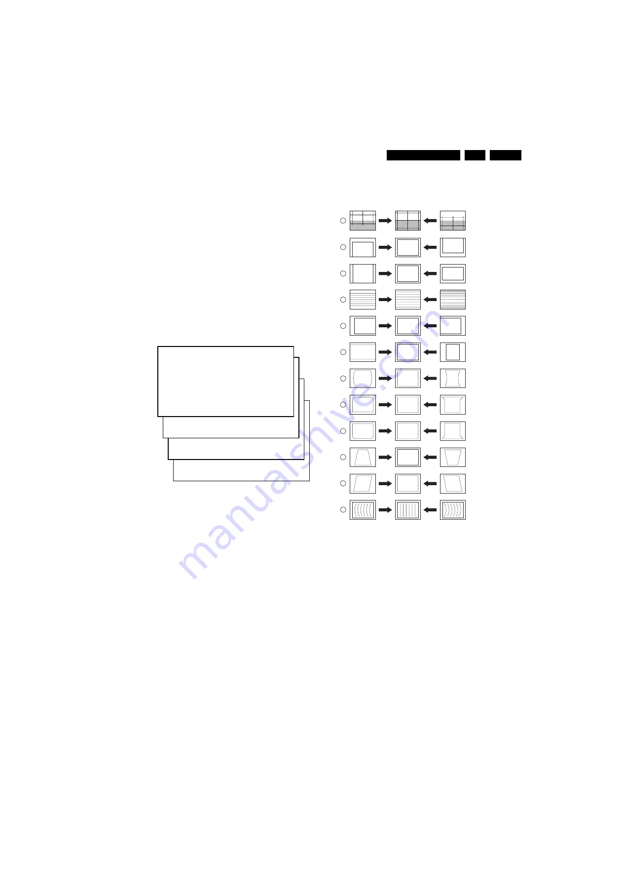
The geometry alignments menu contains several items to align
the set, in order to obtain correct picture geometry.
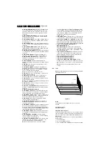
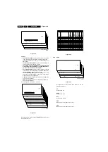
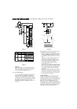
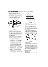
Figure 8-9
Connect an external video pattern generator to the aerial input
of the TV-set and input a crosshatch test pattern. Set the
generator amplitude to at least 1 mV and set frequency to
475.25 MHz (PAL/SECAM) or 61.25 MHz (NTSC).
1.
Set 'Smart Picture' to NATURAL (or MOVIES).
2.
Activate the SAM menu (see chapter 5).
3.
Go to the GEOMETRY sub menu.
4.
Choose HORIZONTAL or VERTICAL alignment
Now you can perform the following alignments:
Horizontal:
•
Horizontal Parallelogram (HP)
Align straight vertical lines
in the top and the bottom; vertical rotation around the
centre.
•
Horizontal Bow (HB)
Align straight horizontal lines in the
top and the bottom; horizontal rotation around the centre.
•
Horizontal Shift (HSH)
Align the horizontal centre of the
picture to the horizontal centre of the CRT.
See also Figure 8-9 numbers 11, 12 and 5.
S A M
N O R M A L
>
(1)
C O O L
>
(2)
W A R M
>
(3)
(1)
N O R M A L
R E D
X X
N O R M A L
G R E E N
X X
N O R M A L
B L U E
X X
(2)
D
C O O L
R E D
X X
D
C O O L
G R E E N
X X
D
C O O L
B L U E
X X
(3)
D
W A R M
R E D
X X
D
W A R M
G R E E N
X X
D
W A R M
B L U E
X X
CL 16532008_0
51
220501
CL 16532044_022.eps
140501
1
2
3
4
5
6
7
8
9
10
11
12
VERT. SLOPE
VERT. SHIFT
VERT. AMPLITUDE
V.S-CORRECTION
HOR. SHIFT
HOR. AMPLITUDE
E/W PARABOLE
UPPER E/W CORNER
LOWER E/W CORNER
E/W TRAPEZIUM
HOR. PARALLELOGRAM
HOR. BOW

