2 - 3
2 - 3
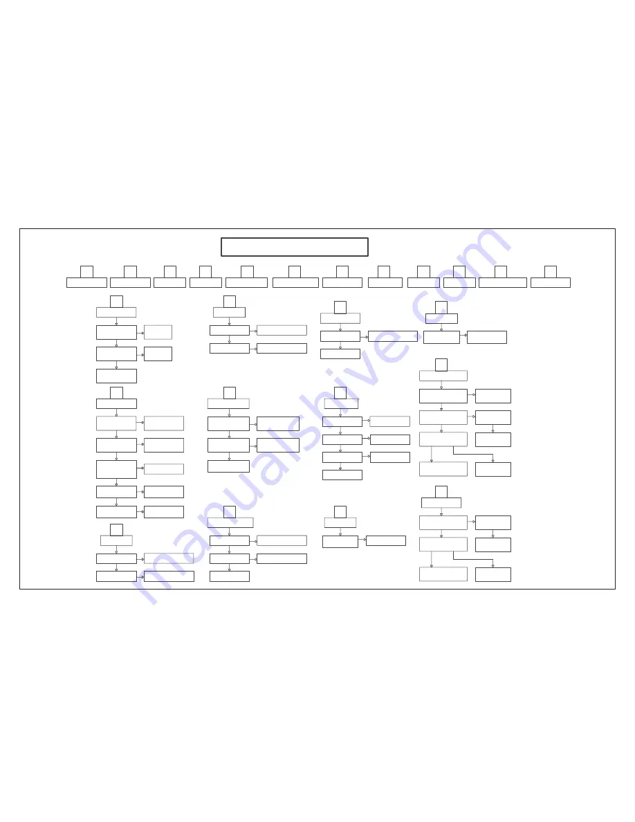
REPAIR INSTRUCTIONS
A
Al l Function No Working
B
All Function No Sound
C
AUX IN No Sound
D
MP3 IN No Sound
E
T UNE R Function No Sound
I
US B No Function
L
DI SC Function No Sound
K
HDMI IN Function No Sound
F
Coaxial in Function No Sound
G
Optical In No Sound
H
Dock In No Sound
MAIN UNIT REPAIR CHART
A
All Function No Working
Check system all cable
is loose or bad IN T
Re-insert and
fix the cable
yes
No
Standby LED
Whether Li ght
No
Check PSU BK 5V
yes
Check VF D PCB Q801
and LED Conjoint part
B
All Function No Sound
Check MA IN PCB FB 5003
w33.2V and at
D5008(+) +5V
Check PSU and Conjoint
No
Part
Check MA IN PCB IC 5002
IC 5003 IC 5004 IC 5005
IC 5007 and their conjoint
yes
part whether OK
Instead same part
No
yes
Check MA IN PCB
IC 3007 (+1.8V )
IC 3006 (+3.3V )
No
Instead same IC 3007
and IC 3006
yes
Check MA IN PCB IC 3008
IC 3005 and their conjoint
part whether OK
Check MA IN PCB IC 5007
Pin9 36 54 whether
Check Q5003 and
No
Conjoint Part
+3.3V
yes
No
Instead same part
C
AUX IN No Sound
yes
Check Signal Source
output whether OK
No
Instead Signal Source
yes
Check IC 3002 Pin11 12
input signal whether OK
No
Check JK 3002 and IC 3002
Pin11/12 conjoint part whether ok
D
MP3 IN No Sound
yes
Check Signal Source
output whether OK
No
Instead Si gnal Source
yes
Check IC 3002 Pin7 8
input signal whether OK
No
Check JK 3002 and IC 3002 P7/8
CN 3002 conjoint part whether ok
E
T UNE R Function No Sound
yes
Check MAIN PCB FM 3001
Pin7/8 Si gnal output
Whether OK
No
Check MAIN PCB FM 3001
Pin5 +5V and their conjoint
part Whether OK
Check MAIN PCB IC 3002
Pin23/24 Signal input
Whether OK
No
Check FM 3001 Pin7/8 and
IC 3002 Pin23/24 their
conjoint part
yes
Check IC 3002
their conjoint part
F
Coaxial in Function No Sound
Check Signal Source
output whether OK
No
Instead Signal Source
yes
Check IC 3003 Pin2
input signal whether OK
No
Check JK 3001 and IC 3003
Pin2 conjoint part
yes
Check IC 3003 and
conjoint part
G
Optical In No Sound
Check IC 3003 Pin1
input signal whether OK
No
Check JK 3001 Pin1 +3.3V a nd
IC 3003 Pin1 conjoint part
yes
Check IC 3003 and
conjoint part
H
Dock In No Sound
Check JK 304 Pin5/8 Si gnal
output whether OK
No
Instead Dock Source
Check IC 3009 Pin1/7 Si gnal
output whether OK
yes
No
Check IC 3009 Pin4 -12V Pi n8
+12V ,and conjoint part
Check IC 3002 Pin9/10 Si gnal
output whether OK
yes
No
Check IC 3009 Pin1/7 , IC 3002
Pin9/10,and conjoint part
yes
Check IC 3002 and
conjoint part
J
WI FI No Function
I
US B No Function
Check MP 3 PCB CN 203
CN 202 US B cable
No
re-insert CN 203 CN 202
and fix the cable
J
WI FI No Function
Whether OK
Check BD PCB CN 203
WI - FI cable
Whether OK
No
re-insert BD PCB CN 203
and fix
the
cable
K
HDMI IN Function No Sound
Check IC 101 Pin88,89,90,91
signal whether OK
No
94,95,96 Data and CL K
Check IC 101 and
their conjoint part
signal whether OK
yes
Check IC 3000 Pin11,12,13,14,
15,16,17 Data and CL K
No
Check IC 3000 pin1,19
whether Low level
No
Check IC 201 pin35 and
their conjoint part
CL K signal whether OK
yes
Check IC 3008 Pin23,24,26,27,
29,30, IC 3010 Pin4 Data and
yes
Check IC 3008 and
their conjoint part
No
Check IC 3000 to IC3008
their conjoint part
L
DI SC Function No Sound
signal whether OK
yes
Check IC 3001 Pin11,12,13,14,
15,16,17 Data and CL K
No
Check IC 3001 pin1,19
whether Low level
No
Check IC 201 pin4 and
their conjoint part
CL K signal whether OK
yes
Check IC 3008 Pin23,24,26,27,
29,30, IC 3010 Pin4 Data and
yes
Check IC 3008 and
their conjoint part
No
Check IC 3001 to IC3008
their conjoint part
Содержание HTS8562/98
Страница 16: ...4 1 4 1 BLOCK DIAGRAM ...
Страница 17: ...4 2 4 2 WIRING DIAGRAM V7 V9 V5 V1 V4 V2 V8 V6 V3 ...
Страница 39: ...9 1 9 1 Mechanical Exploded View Note A1 3 5 8 24 29 33 36 RC MIC FM ...
Страница 40: ...10 1 REVISION LIST Version 1 0 Initial release Version 1 1 HTS8562 12 combine with HTS8562 98 ...


