1 - 1
HTS6120/
55
©
Copyright 2009 Philips Consumer Electronics B.V. Eindhoven, The Netherlands
All rights reserved. No part of this publication may be reproduced, stored in a retrieval system or
transmitted, in any form or by any means, electronic, mechanical, photocopying, or otherwise
without the prior permission of Philips.
Published by
RY0946
Service Audio Printed in The Netherlands Subject to modification
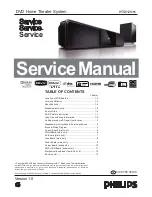
DVD Home Theater System
Version 1.0
TABLE OF CONTENTS
Location of PCB Boards ............................................ 1-2
Versions Variation ...................................................... 1-3
Measurement Setup .................................................. 1-5
Specifications ............................................................ 1-4
Service Aids .............................................................. 1-6
ESD & Safety Instruction .......................................... 1-7
Lead-free soldering Information ................................ 1-8
Setting procedure & Repair Instructions........................ 2
Disassembly Instructions & Service positions .............. 3
Block & Wiring Diagram ................................................ 4
Control Board (main unit) .............................................. 5
MAIN Board (main unit).................................................. 6
Service Manual
Service
Service
Service
AV Board (main unit)...................................................... 7
Ipod Board (main unit) .................................................. 8
Motor Board (main unit) ................................................ 9
Power Board (subwoofer) ............................................ 10
AMP+USB Board (subwoofer) .................................... 11
Mechanical Exploded View & Part List ........................ 12
Revision List ................................................................ 13
GB
Chapter
3139 785 35190
Made for
iPod
Содержание HTS6120/55
Страница 2: ...MAIN UNIT SUBWOOFER 1 2 LOCATION OF PCB BOARDS ...
Страница 7: ...1 7 ...
Страница 8: ...1 8 ...
Страница 16: ...4 1 4 1 BLOCK DIAGRAM Main Unit D F V v i r D er PT 1 1 3 6 2 ...
Страница 17: ...4 2 4 2 WIRING DIAGRAM Main Unit 9 9 3 50 32 3 86 3 ...
Страница 18: ...4 3 4 3 BLOCK DIAGRAM Subwoofer TI5342LA TI5342LA TI5342LA TI5342LA TAS5508 ...
Страница 31: ...8 1 8 1 IPOD BOARD main unit TABLE OF CONTENTS Circuit Diagram 8 2 PCB Layout View 8 3 ...
Страница 36: ...9 3 9 3 PCB LAYOUT TOP VIEW CN308 A1 CN309 A1 SW1 A1 SW2 A1 A A 1 1 ...
Страница 37: ...9 4 9 4 PCB LAYOUT BOTTOM VIEW C348 A1 C349 A1 C350 A1 C351 A1 FB358 A1 FB359 A1 FB360 A1 FB361 A1 A A 1 1 ...
Страница 46: ...12 1 12 1 Mechanical Exploded View main unit ...
Страница 47: ...12 2 12 2 Mechanical Exploded View subwoofer S9 SW28 SW27 SW25 SW24 S6 SW23 S4 SW22 SW26 SW31 S3 S3A S3B 29 ...
Страница 51: ...13 1 REVISION LIST Version 1 0 Initial release Alternative Codes Safety Symbol ...


