3 - 3
3 - 3
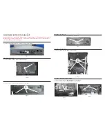
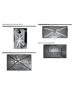
Dismantling of the Subwoofer AMP Board
1) Loosen 4 screws “S” on the top of subwoofer AMP board as shown in fi gure 19.
S
Figure 19
SERVICE POSITIONS (SUBWOOFER)
DISASSEMBLY INSTRUCTIONS-SUBWOOFER
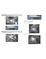
Dismantling of the Subwoofer Rear Panel
1) Loosen 9 screws “Q” at the subwoofer rear panel as shown in fi gure 17.
Dismantling of the Power Board
1) Loosen 5 screws “R” on the top of power board as shown in fi gure 18.
R
Figure 17
Figure 18
Q
Содержание HTB9245D
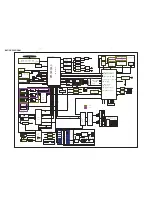
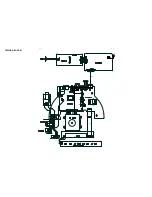
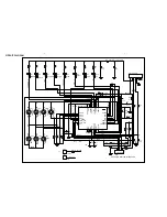
Страница 17: ...4 2 4 2 WIRING DIAGRAM V1 V4 V2 V3 V5 SV2 V10 CN901 AC SOCKET SV1 LCD ...
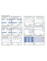
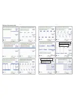
Страница 25: ...6 3 6 3 Waveforms for measure point ...
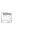
Страница 26: ...6 4 6 4 Waveforms for measure point IB612 QJO43 IENJ SY TEB IENJ SY JO2 IB612 QJO44 IENJ SY TDM IENJ SY JO2 ...
Страница 27: ...6 5 6 5 Waveforms for measure point IB612 QJO55 INDV TEB ...
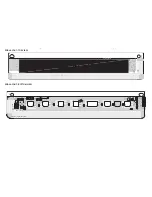
Страница 28: ...7 1 7 1 TOUCH BOARD TABLE OF CONTENTS Circuit Diagram 7 2 PCB Layout Top Bottom View 7 3 ...
Страница 35: ...9 1 9 1 LCD BOARD TABLE OF CONTENTS Circuit Diagram 9 2 PCB Layout Top Bottom View 9 3 ...
Страница 39: ...10 2 10 2 Mechanical Exploded View Subwoofer SW1 SW2 SW3 SW4 SW12 SW13 SW5 SW6 SW7 SW8 SW9 SW10 SW11 ...
Страница 40: ...11 1 REVISION LIST Version 1 0 Initial release ...


