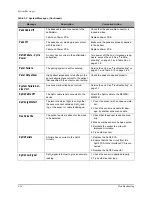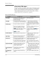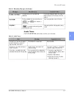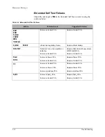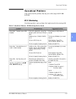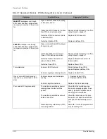
Diagnosing Internal Failures
3
-
6
Troubleshooting
z
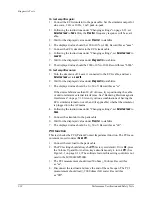
To store the configuration settings on a data card, select
Save Settings
to Data Card
and press
. When prompted with
Save Settings to
Data Card?
press
.
z
To load configuration settings from a Data Card, select
Load Settings
from Data Card
and press
. When prompted with
Load Settings
from Data Card?
press
.
z
To exit Configuration Mode, turn the unit off. Wait 2 seconds.
Remove the Data Card by pressing the black eject button and pulling
the Data Card from the compartment.
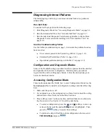
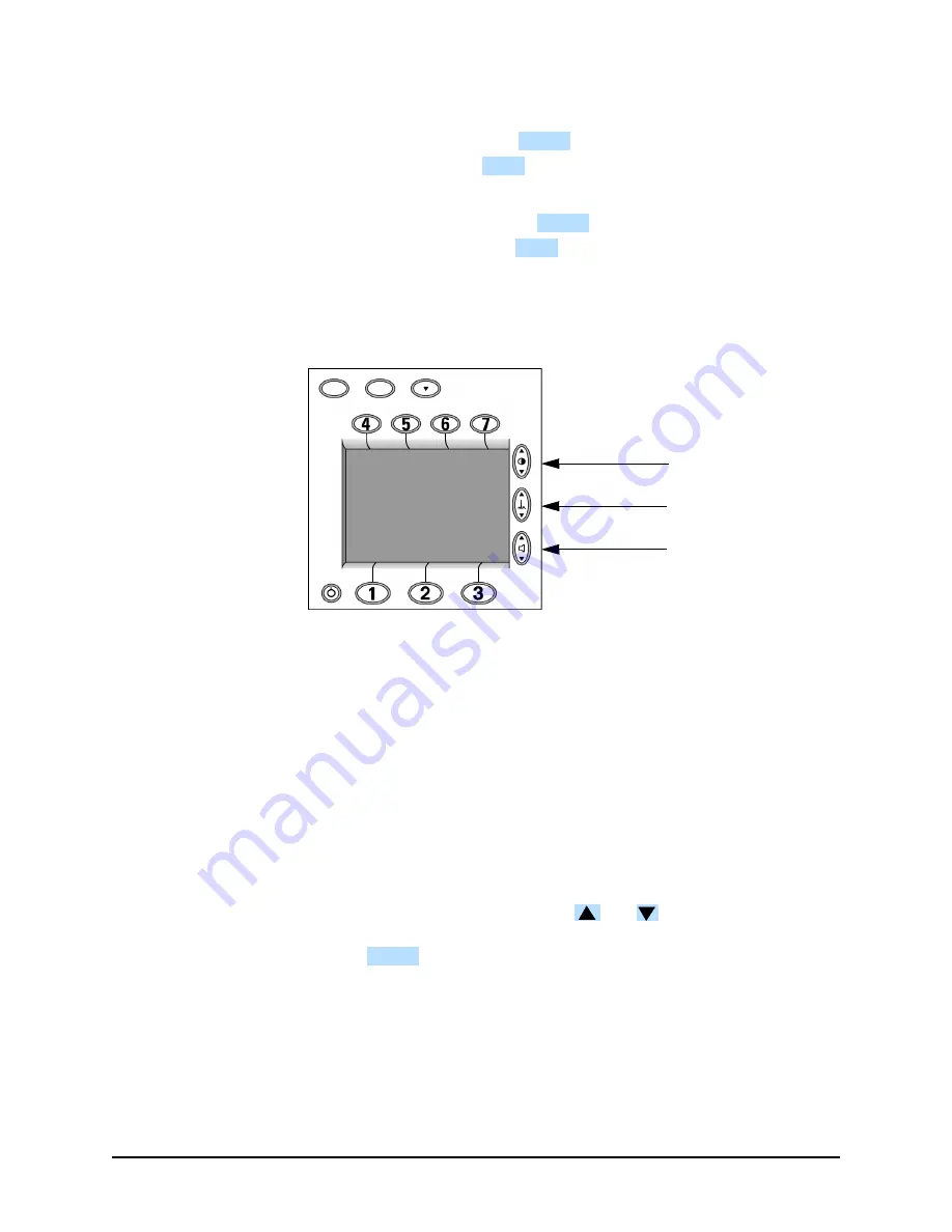
Figure 3-1 Softkey Numbers
Accessing Diagnostic Mode
These instructions describe how to enter Diagnostic Mode. The Diagnostic
Mode allows printing of the System Log (see "Printing the System Log" on
page 3-6). It also allows running the Extended Self Test and other Diagnostic
Tests. For details of running these tests, see "Diagnostic Tests" on page 2-16.
1. Make sure the power is off.
2. Press softkeys 4 and 6 at the same time, and hold them down while turn-
ing the power on. See Figure 3-1 for softkey numbering.
3.
Wait for the Diagnostic software to initialize. This will take several
seconds. The unit is ready to proceed when the screen cursor
responds to softkey inputs.
z
To select a function, press the
and
softkeys to move up or
down the list until the desired function is highlighted. Then press the
softkey to begin that function.
z
To exit Diagnostic Mode, turn the instrument off.
Printing the System Log
These instructions describe how to print the system log, which includes the
unit’s serial number, hardware configuration, and a listing of error codes.
1. Enter Diagnostic Mode as described in "Accessing Diagnostic Mode".
ENTER
SAVE
ENTER
LOAD
ECG Size
Volume
Contrast
ENTER
Содержание Heartstart XLT
Страница 1: ...H E A R T S TA R T X LT S e r v i c e M a n u a l M 3 5 0 0 B M 5 5 0 0 B ...
Страница 2: ......
Страница 3: ...Service Manual M3500B HeartStart XLT M5500B Heartstart 4000 Defibrillator Monitor ...
Страница 6: ......
Страница 16: ......
Страница 20: ......
Страница 52: ......
Страница 110: ...Opening the Sealed Case 4 24 Removal and Replacement Figure 4 13 Battery Connector Location 4 Pin Battery Connector ...
Страница 195: ...M3500B M5500B Service Manual 6 17 System Functional Descriptions 6 Figure 6 3 Power Distribution and Fusing ...
Страница 205: ...M3500B M5500B Service Manual 7 9 Waveforms 150J continued 7 Waveforms 150J continued 150J 75 ohms 150J 100 ohms ...
Страница 206: ...Waveforms 150J continued 7 10 Specifications Waveforms 150J continued 150J 125 ohms 2ms div 150J 125 ohms 5 ms div ...
Страница 208: ...Waveforms 200J continued 7 12 Specifications Waveforms 200J continued 200J 75ohms 200J 100ohms ...
Страница 216: ......
Страница 223: ......
Страница 224: ...M3500 90900 Printed in USA February 2003 Second Edition M3500 90900 2 ...

