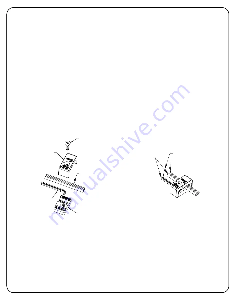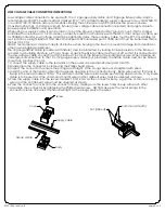
screw
cover
supply cable
fixture cable
body
hot (ribbed)
common (smooth)
LOW VOLTAGE CABLE CONNECTOR INSTRUCTIONS
Low voltage cable connector to be used with 10 or 12 gauge supply cable and 18 gauge fixture cable. Hadco
recommends using SPT-3 water resistant (marked "WA", "W" or similar marking) supply cable such as our SCW500-10
or our SCW100-12. Hadco also recommends ordering the entire system, which includes the power console
(maximum 25 Amps, 15 Volts per circuit), fixture(s) (low voltage cable connector included) and supply cable to
ensure proper installation and operation.
When using our supply cable, it can be laid on top of the ground, placed under "ground cover" (that is, shallow
burial less than 6 inches or 15.2 cm deep), or directly buried in accordance with the NEC. If not using our cable, per
UL 1838-Standard for Low Voltage Landscape Lighting Systems, the secondary cable must be SPT-3 or suitable for
wet locations, sunlight resistant and direct burial per UL 493 and sized per UL 1838, and it must be buried less than 6
inches (15.2 cm).
Hadco recommends a minimum depth of 4 inches when burying in the lawn to prevent damage from aerators or
other lawn plugging equipment.
The 18 gauge fixture cable (provided with fixture) must be protected by routing in close proximity to the fixture or
secured to a building structure such as a house or deck. The fixture cable must be cut off so that it is connected to
the low voltage cable connector within 3 inches (7.6 cm) of the fixture or the building structure. When making an
underground connection to the 10 or 12 gauge supply cable (not provided), the fixture cable must not be buried
more than 3 inches (7.6 cm).
1. Connect the supply cable to the terminals on the power console (transformer) and turn ON.
2. Disassemble the connector by removing the Phillips head screw.
3. Inspect the connector to ensure the prongs are straight. If the prongs are bent, straighten with pliers.
4. Insert the end of the fixture cable into the square opening in the connector body. Bend wire over so that wire is
laying in the recess marked '18 GA'. This will help hold the wire in place while performing steps 5 and 6. Only 2-wire
cable is to be used and the common (smooth) wire and hot (ribbed) wires must be oriented as shown.
5. Press the supply cable into the recess marked '10,12/2 GA' on the connector body. Again the common (smooth)
wires and the hot (ribbed) wires must be oriented as shown.
6. Press the connector cover onto the connector body, making sure the screw holes line up with each other.
7. Assemble the connector by tightening the Phillips head screw. NOTE: Make sure the metal prongs in the
connector pierce all 4 wires; the fixture will light as the prongs pierce the wires.
page 3 of 3
32001444, revision B


