3139 116 19452 (ENG)
7
PREPARATION
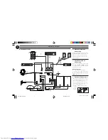
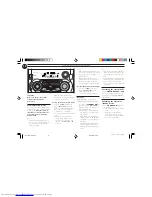
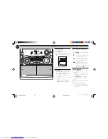
Rear Connections
AM ANTENNA
F
AUX/CDR IN
H
SUB-
WOOFER
OUT
DIGITAL
OUT
LINE OUT
AUDIO OUT
L
R
L
R
H I G H P OW E R S U B WO O F E R
SU
BW
OOFER
LEVEL CONT
ROL
STANDBY ON
CUT OFF FREQUENCY
60Hz
150Hz
MIN
MAX
AUDIO IN
G
J
B
AC
MAINS
~
REAR
SURROUND
L
surr.
R
surr.
L
+
–
R
–
+
D
A
I
C
FRONT
L
R
L
+
–
R
–
+
FM ANTENNA 300
Ω
E
CENTER
CENTER
+
–
A
AM Loop Antenna
Connection
Connect the supplied loop antenna to
the AM ANTENNA terminal. Place the
AM loop antenna far away from the
system and adjust its position for the
best reception.
B
FM Wire Antenna
Connection
Connect the supplied FM wire antenna
to the FM ANTENNA 300
Ω
terminal.
Adjust the position of the FM antenna
for the best reception.
Outdoor Antenna
For better FM stereo reception,
connect an outdoor FM antenna to the
FM ANTENNA 300
Ω
terminal using a
300
Ω
dipole wire.
C
Speakers Connection
• Connect the right speaker to Front
terminal R, with the colored wire to
+
and the black wire to
-
.
• Connect the left speaker to Front
terminal L, with the colored wire to
+
and the black wire to
-
.
• Clip the stripped portion of the
speaker
wire as
shown.
unlock
lock
12 mm
pg 01-28/P78/37-Eng2
12/20/99, 2:23 PM
7

