BRIEF INTRODUCTION OF THE AF9 BOARD
The AF9 Board consists of the following features :
a.
TDA7468D
TDA7468D (7501) provides the basic sound processing - loudness, bass, treble, volume & mute controls and source selection - TUNER,
TAPE, CD & AUX including Mic mixing for the set.
Sound features such as ALC, DBB, DSC and IS are controlled by the microprocessor IC on the Front Board via I
2
C Bus.
Undesirable noise during source switching are muted off by via the software of the microprocessor IC on the Front Board.
b.
MIC MIXING
Simple Mic mixing is provided by pin 2 of TDA7468D. During Mic mixed a 1nF capacitor is connected across this pin to ground instead
of a chip connector(0R).
c.
DOLBY PRO LOGIC (DPL) INTERFACE
The AF9 Board has provisions to cater for DPL. External DPL Board would be required.
d.
LINE OUT
Line out cinch socket (1504) is catered including tranistors muting circuitry.
e.
SUB-WOOFER OUT
Sub-woofer out cinch socket (691) for connection to active sub-woofer speaker is catered.
f.
INCREDIBLE SURROUND (IS)
The AF9 provides 2 possible IS namely:
a) Simple IS using TDA7468D with addition of passive network.
b) Full IS using transistor circuitry to create phase shifting and spatial effect.
g.
HEADPHONE AMPLIFIER
Headphone amplifier NJM4556AM (7601) is provided after the Sound processor (7501) to drive 32 ohm to 1kohm headphone.
h.
M62320FP
The M62320FP (7403) I
2
C Expander provides additional controls reqired.
i.
CD STANDBY CONTROL
Transistors 7401 & 7402 ensures the +5V_CD supply is switched only during CD mode.
j.
CD DIGITAL OUT
CD Digital out cinch socket (1801) for connection to external digital audio decoders.
AF9 BOARD
TABLE OF CONTENTS
Brief Introduction of the AF9 Board .......................................... 12-1
Variation Table .......................................................................... 12-1
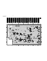
Chip layout Main part ............................................................... 12-2
Component Main part ............................................................... 12-3
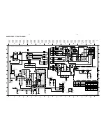
Source Selection and Sound Processing Circuit ..................... 12-4
Headphone Amplifier & I
2
C Expander Circuit .......................... 12-5
Digital Out and Interconnection Circuit .................................... 12-6
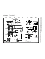
Video Out Part - Layouts & Circuit diagram ............................. 12-7
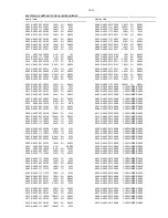
Electrical parts list .................................................................... 12-7
12-1
12-1
/21
/21M
/22
/30
/33
/34
/37
Line In
x
x
x
x
x
x
x
Line Out
-
-
-
-
-
-
-
Sub-woofer Out
-
-
-
-
-
-
-
Digital Out
-
-
-
-
-
-
-
Video Out
-
-
-
-
-
-
-
Mic mix / Mic Detect
x
x
-
-
x
-
-
Simple IS
x
x
x
x
x
x
x
Full IS
-
-
-
-
-
-
-
Dolby ProLogic (DPL)
-
-
-
-
-
-
-
Voice Control (VC)
-
-
-
-
-
-
-
VARIATION TABLE:
Type /Versions:
FW-C399
Features:


