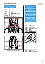
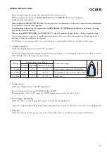
Philips EasyCare GC8328 Скачать руководство пользователя страница 3

GC8328

3-8

STAND

IRON

L

N

Boiler Electronics

On/Off switch
Steam up switch
Steam down switch

Thermal
Fuse

Thermal
Fuse

L

N

L

S

N

Boiler
Heating
Element

Reed

Switch

Thermistor

1

Ther-
mostat

Heating
Element

Pump M

Electro-
valve

Thermistor

2

Power LED x 1
Steam LEDs x 4
Tank Empty LED x 1
Rinse Reminder LED x1

Fig 4 .  Electrical diagram

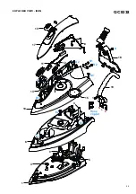
PARTS LIST - IRON  &  ELECTRICAL DIAGRAM

Pos

Service code

Description

1
3
4
5

6
8
9

10

11
12
13
14

15
17
18
19

4239 021 41291
4239 015 59301
4239 010 10281
4239 015 70150

4239 026 46591
4239 021 36861
4239 026 13220
4239 021 65042

4239 021 31790
4239 026 46601
4239 026 46611
4239 010 09290

4239 021 61321
4239 026 46621
4239 026 21895
4239 021 65051

Soleplate assy 230 V  (Steamglide-Non SOS)
Braided rubber hose  (Basic)
Hose clip-braided rubber hose
Ryton ring

Soleplate cover
Lamp mounted assy
Thermostat bush
Housing printed

Microswitch assy
Trigger (Dark blue)
Steam lock  (Dark Blue)
Trigger spring

Thermostat dial assy  (Blue)
Inlay (Dark blue)
Backplate (White)
Hose cord mounted assy

Содержание EasyCare GC8328

Страница 1: ...een repaired it should function properly and has to meet the safety requirements as officially laid down as this moment TECHNICAL INFORMATION Voltage 220 240 V Frequency 50 60 Hz Power Iron 800 W Boiler 1370 W Dimension F box 350 x 350 x 250 mm L x W x H Weight with packing 6 4 kg Water advice If the tap water in your area is very hard it is advisable to mix the tap water with an equal amount of d...

Страница 2: ...e Lamp assy Blue Lamp assy N S Fig 2 Wiring at rear HOUSING Part 2 INLAY 17 STEAM LOCK 13 LAMP ASSY 8 MICROSWITCH ASSY 11 TRIGGER 12 THERMOSTAT DIAL ASSY 15 HOUSING PRINTED 10 SOLEPLATE COVER 6 THERMOSTAT BUSH 9 BRAIDED RUBBER HOSE 3 SOLEPLATE ASSY 1 Remove Screw A Disassemble BACKPLATE 18 Release Inlay rear catch Disassemble INLAY 17 Disassemble STEAM LOCK 13 Disassemble MICROSWITCH ASSY 11 Remov...

Страница 3: ... 4 5 6 8 9 10 11 12 13 14 15 17 18 19 4239 021 41291 4239 015 59301 4239 010 10281 4239 015 70150 4239 026 46591 4239 021 36861 4239 026 13220 4239 021 65042 4239 021 31790 4239 026 46601 4239 026 46611 4239 010 09290 4239 021 61321 4239 026 46621 4239 026 21895 4239 021 65051 Soleplate assy 230 V Steamglide Non SOS Braided rubber hose Basic Hose clip braided rubber hose Ryton ring Soleplate cover...

Страница 4: ...GC8328 4 8 13 14 17 11 10 6 4 9 1 3 12 15 18 19 5 A S N L E B1 B2 D3 Hose clip a E2 D2 D1 E1 E3 8 C EXPLODED VIEW IRON ...

Страница 5: ...38 Disassemble STAND TOP 24 Remove Screws H1 H2 Disassemble BOILER ASSY 20 Remove Screws J1 J2 Disassemble FRONT PANEL PRINTED 31 K1 K2 K3 12 11 10 9 Pos Connected to Pos Connected to 9 Reed switch 11 Thermistor 10 Power board 12 Hosecord Black Fig 5 Connections on CONTROL BOARD 41 Remove Connections 9 10 11 12 Fig 5 Remove Screws at K1 K2 K3 Fig 5 Disassemble CONTROL BOARD 41 21 20 15 14 18 13 22...

Страница 6: ...461 4239 010 10260 4239 022 62500 4239 026 21930 4239 021 61161 4239 015 59121 Boiler assy EE Electrovalve Electrovalve mesh Stand bottom EE Tulip Blue Stand top assy White Spacer bottom Spacer top Pump assy Inox clamp Safety cap assy Nipple plate Front panel printed Power button cap Blue Pos Service code Description 33 34 35 36 37 38 39 40 41 42 43 44 4239 021 31820 4239 015 56160 4239 021 31970 ...

Страница 7: ...GC8328 7 8 F1 G2 H1 J1 K2 J2 K1 K3 H2 G3 G1 F3 G4 F2 30 37 35 42 31 23 32 41 36 38 39 43 29 44 27 40 34 24 28 21 22 33 20 26 25 EXPLODED VIEW STAND ...

Страница 8: ... 1 Soleplate temperature Check that soleplate temperature is within IEC requirement Measure the temperature of the soleplate after the iron has reached steady state i e connected to the mains for at least 15 minutes The table below shows the temperature requirement Marking Soleplate temperature Deg C Material for example Test point Minimum Maximum Nominal Tolerance 1 dot 70 120 95 25 Acetate elast...

Отзывы: