Service Modes, Error Codes, and Fault Finding
EN 10
DPTV565 AA
5.
5.
Service Modes, Error Codes, and Fault Finding
Index of this chapter:
5.1 Test Conditions
5.2 Service Modes
5.3 Problems and Solving Tips (related to CSM)
5.4 ComPair
5.5 Error Codes
5.6 The ”Blinking LED” Procedure
5.7 Trouble Shooting Tips
5.1
Test Conditions
The chassis is equipped with test points printed on the circuit
board assemblies. They refer to the diagram letters. The
numbering is in a logical sequence for diagnostics. Always start
diagnosing (within a functional block), in the sequence of the
relevant test points for that block.
Measurements should be performed under the following
conditions:
•
Service Default Mode.
•
Video: Colour Bar Signal.
•
Audio: 3 kHz left, 1 kHz right.
5.2
Service Modes
Service Default Mode (SDM) and Service Alignment Mode
(SAM) offer several features for the service technician, while
the Customer Service Mode (CSM) is used for communication
between a Philips Customer Care Centre (P3C) and a
customer.
There is also the option of using ComPair, a hardware interface
between a computer (see requirements below) and the TV
chassis. It offers the ability of structured troubleshooting, test
pattern generation, error code reading, software version
readout, and software upgrading.
Minimum requirements: a Pentium processor, Windows 95/
98, and a CD-ROM drive (see also paragraph “ComPair”).
5.2.1
Service Default Mode (SDM)
Introduction
The Service Default Mode (SDM) is a technical aid for the
service technician. The Service Default Mode (SDM)
establishes fixed, repeatable settings of customer controls,
which allow consistent measurements to be made. The SDM
also initiates the blinking LED procedure and, if necessary,
overrides the 5 V protection.
The SDM places the set in the following pre-defined conditions:
•
Tuning frequency set to 475.25MHz.
•
Volume level set to 25% (of the maximum volume level).
•
Other picture and sound settings set to 50% (mid-range).
The following functions are turned OFF while in SDM:
•
Timer
•
Sleep timer
The following functions are disabled during SDM (and enabled
after leaving SDM):
•
Parental lock
•
Blue mute
•
Hospitality Mode
•
No-ident Timer (normally the set is automatically switched
off when no video signal (IDENT) is received for 15
minutes).
All other controls operate normally.
How to Enter SDM
To enter the Service Default Mode, press the following key
sequence on the remote control transmitter
“0-6-2-5-9-6”-MENU. Do not allow the display to time out
between entries while keying the sequence.
Upon entry into the Service Default Mode, the letters "SDM" will
be displayed at the upper right corner of the screen.
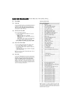
Figure 5-1 SDM menu
Special SDM functions
•
Access to normal user menu: Pressing the "MENU" button
on the remote control switches between the SDM and the
normal user menus (with the SDM mode still active in the
background).
How to Exit SDM
To exit the Service Default Mode, press the Power (standby)
button.
Note: To save the error codes, unplug the AC power cord
without turning off the set. When the power is turned back on,
the Service Default Mode will still be active.
5.2.2
Service Alignment Mode (SAM)
The Service Alignment Mode (SAM) is used to align the set
and/or adjust the option settings and to display/clear the error
code buffer values.
How to Enter SAM
•
To enter the Service Alignment Mode (SAM), press the
following key sequence on the remote transmitter:
“0-6-2-5-9-6”-[i+]. Do not allow the display to time out
between entries. After entering SAM with this method a
service warning will appear on the screen, you can
continue by pressing any digit key on the RC.
•
Use the DST-emulation feature of ComPair.
•
Press the ALIGN button on the DST while the set is in the
normal operation
After entering this mode, “SAM” the following menu structure
will appear on the screen:
SDM
HRS: 120E SWID: HDR: 1AP1-5.15
ERR: 14 13 31 30 17 16 23
E_15000_061.eps
141004
Содержание DPTV565 AA
Страница 27: ...Circuit Diagrams and PWB Layouts 27 DPTV565 AA 7 Layout SSB Top Side E_15000_133 eps 191004 8204 000 6507 3 ...
Страница 29: ...Circuit Diagrams and PWB Layouts 29 DPTV565 AA 7 Layout SSB Bottom Side E_15000_134 eps 191004 8204 000 6507 3 ...
Страница 41: ...Circuit Diagrams and PWB Layouts 41 DPTV565 AA 7 Layout SSM Part 1 Bottom Side F_15020_011a eps 110305 Part 1 ...
Страница 42: ...42 DPTV565 AA 7 Circuit Diagrams and PWB Layouts Layout SSM Part 2 Bottom Side Part 2 F_15020_011b eps 110305 ...
Страница 43: ...Circuit Diagrams and PWB Layouts 43 DPTV565 AA 7 Layout SSM Part 3 Bottom Side F_15020_011c eps 110305 Part 3 ...
Страница 44: ...44 DPTV565 AA 7 Circuit Diagrams and PWB Layouts Layout SSM Part 4 Bottom Side F_15020_011d eps 110305 Part 4 ...
Страница 72: ...72 DPTV565 AA 7 Circuit Diagrams and PWB Layouts Personal Notes E_06532_013 eps 131004 ...
Страница 119: ...Revision List EN 119 DPTV565 AA 11 11 Revision List Manual xxxx xxx xxxx 0 First release ...


